¶ Goal(s) of the study
These FEA simulations were performed in order to have a better insight on the behavior of a module under compression, and more specifically in buckling. Linear buckling simulations help us understand the different modes of buckling of the module and demonstrate the usefulness of ABRs.
¶ 21410X_Internal_Structure_Mockup
¶ Geometry
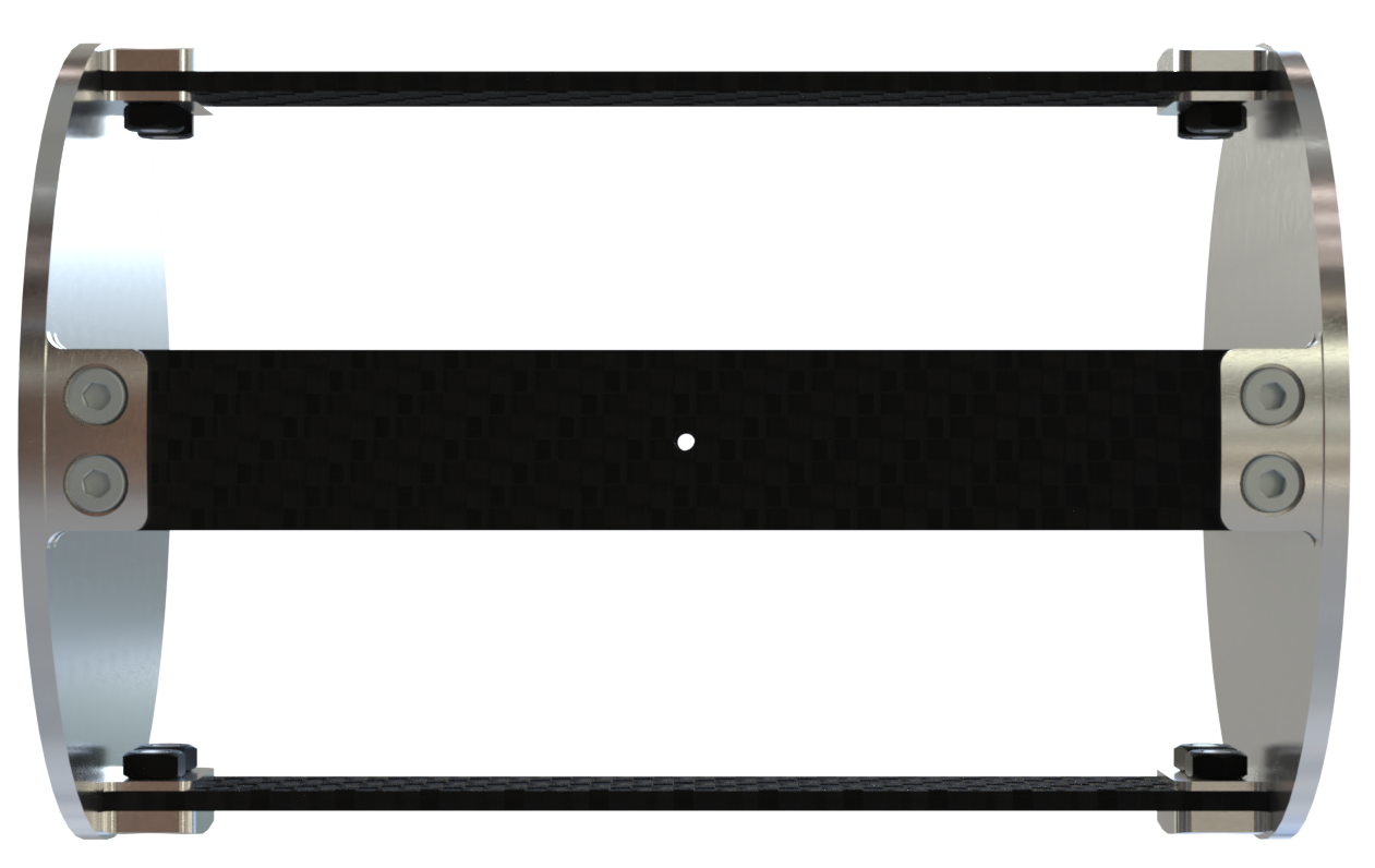
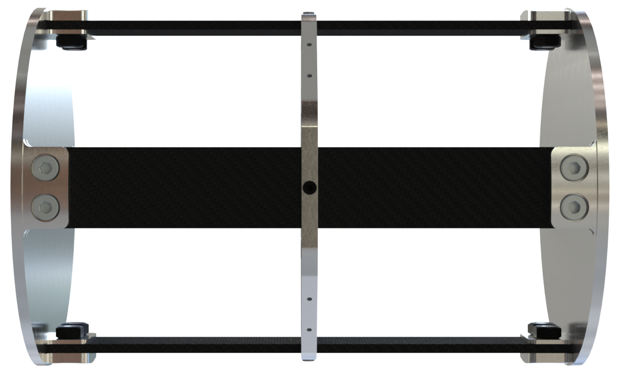
The geometry used for this simulation is the whole module for avionics bay, composed of four CFRP rods, two couplers at each end (simplified for this simulation with flat surfaces instead of the coupler interface) and one ABR. For the purpose of this study, one simulation will be carried out with the ABR, and the other one without it.
To simplify the contacts, which are not the subject of study here, the screws and nuts are removed.
 |
 |
|---|
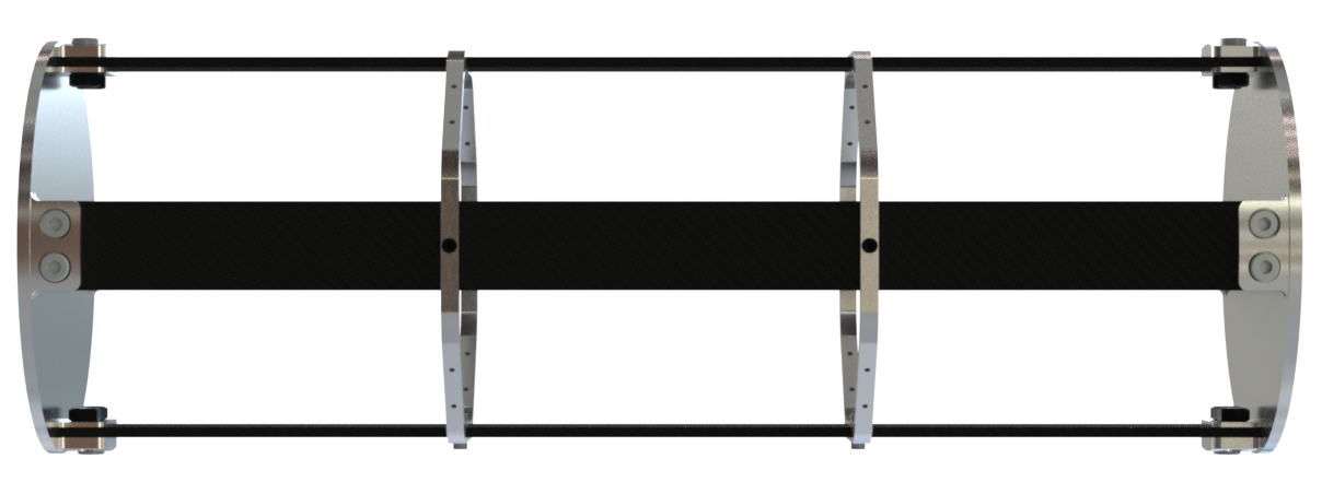
Since the compressive test will also be done on the module for the pressurant bay, simulations are performed on this module. Pressurant bay's module is composed of longer CFRP rods and two ABRs.
¶ Function
This module, just like the others present in the rocket, must ensure structural integrity of the rocket and supports all loads applied to it.
¶ Material
The ABR and both couplers are in aluminum 2050-T6.
The rods are made of CFRP whose layup is described in 2024_C_ST_CFRP-PLATE_MAP.
¶ Load case
The module must withstand all the loads applied to the rocket. This analysis focuses on lift off, when the rocket is subjected to compressive forces and must resist buckling.
- 2024_C_SE_ST_REQ_31
The structural load-bearing elements shall withstand axial compression loads of [15000]N. - 2024_C_SE_ST_REQ_37 Margins of safety for simulation validation
Unless specified otherwise, all parts shall be designed to withstand their design load with an additionnal Margin of Safety (relative to the elastic limit or other applicable failure criterion) depending on the part's nature: MoS 0.25 for all static simulations, MoS 3 for all buckling load cases, MoS 3 for all parts designed via generative algorithms.
¶ Parts List
As contacts are not the limiting factors nor the goal of this simulation, the screws and nuts have been removed to simplify the simulations and avoid singularities in the results.
The contacts are then simply defined as "bonded".
¶ Finite Element Analysis
¶ Software
- ANSYS Mechanical
¶ Type of simulation
- Linear buckling
¶ Inputs
mmNS mm-ton-N-Nmm-MPa-mm^4-mJ
The couplers doesn't have the coupler interface, only a flat surface instead.
The screws and nuts are removed to simplify the contacts.
Otherwise, the geometries are kept as is.
¶ Aluminum alloy 2050 T6
| Density (g/cm^3) | Young's Modulus (GPa) | Poisson's ratio |
|---|---|---|
| 2.7 | 76.5 | 0.33 |
¶ CFRP
The CFRP properties have been defined using ACP.
The properties for the UD and woven plies are:
| Material | Density (g/cm^3) |
|---|---|
| UD | 1.47 |
| Woven | 1.49 |
| | Elastic (Engineering constants) |||||||||
| Material | E1 | E2 | E3 | Nu12 | Nu13 | Nu23 | G12 | G13 | G23 |
|---|---|---|---|---|---|---|---|---|
| UD | 137000 | 10500 | 10500 | 0.3 | 0.3 | 0.51 | 5200 | 5200 | 3476.82 |
| Woven | 49000 | 49000 | 10000 | 0.05 | 0.35 | 0.35 | 5000 | 4500 | 4500 |
In ACP, the layup from 2024_C_ST_CFRP-PLATE_MAPwas defined, which gave the following properties for the CFRP rods using an orthotropic model:
| Density (g/cm^3) | E1 | E2 | E3 | Nu12 | Nu13 | Nu23 | G12 | G13 | G23 |
|---|---|---|---|---|---|---|---|---|
| 1.5 | 88074 | 17739 | 10000 | 0.3 | 0.3 | 0.3 | 3500 | 4081.6 | 3192.2 |
Linear buckling analysis so this is stationnary.
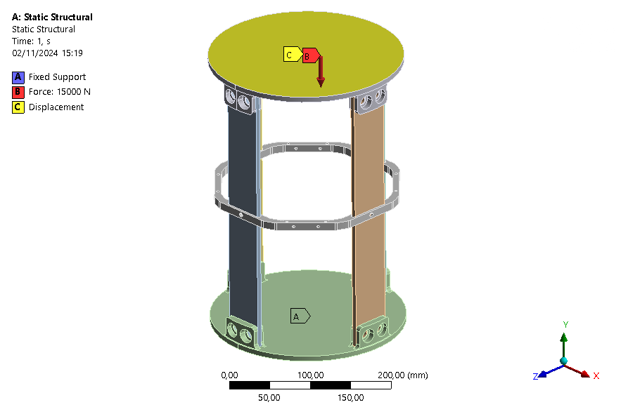
One end of the module is fixed and on the other end a force of 15kN (defined by the requirements) is applied on the surface of the coupler.
Moreover, since we want a simulation as close as a compression test with a press, the displacements in the X-axis and Z-axis are fixed.
|:--- :---
:---
| Real case | Model |
| Blocked by the lower platform of the press | Fixed |
|Pushed by the high press platform | Horizontal displacements fixed + force |
This simulation is set up as in a compression test, in order to compare later on with actual tests that will be carried out.
For the purpose of a linear buckling analysis, first a static structural simulation is performed. Since it is a "classic" simulation, no nonlinearities are introduced.
Using the results from the static structural simulation, the eigenvalue buckling analysis is performed. The negative buckling loadfactors are excluded.
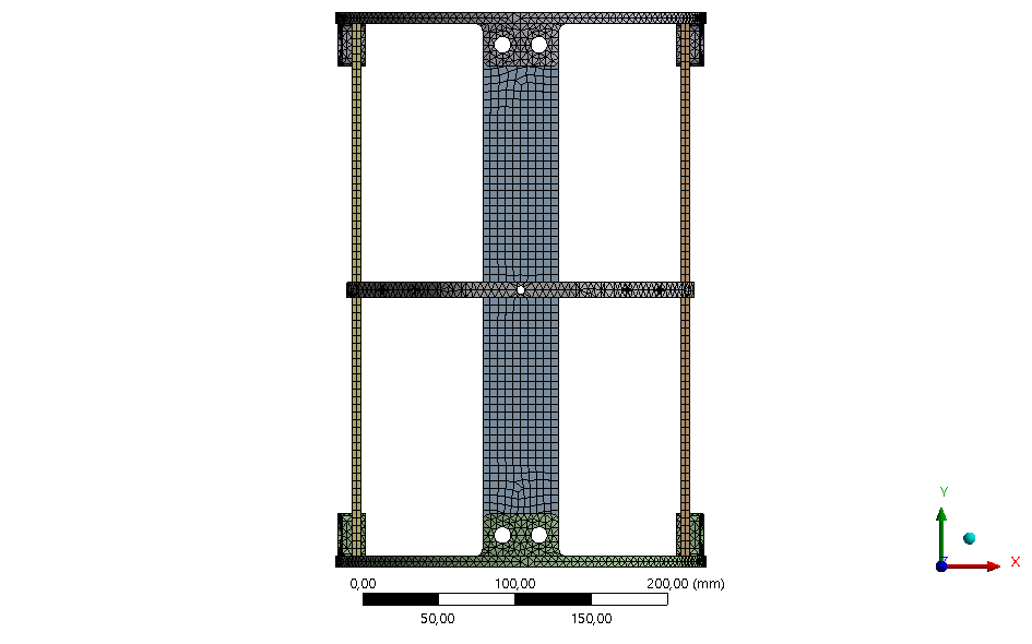
¶ Mesh
The geometries are 3D solid, so element shape is hex with a quadratic order.
Since the goal of the simulation is to observe the general behavior of the module, the mesh is not refined at particular locations.
The "Body sizing" tool is used separately for the couplers, the ABR and for the four rods. A mesh of 5mm is defined for the couplers and the mesh refined is for the rods and ABR since most of the stress is on these parts.
The first buckling loadfactor is used for the mesh independency test.
|:---:---:---:---:---
|Size|10|7.5|5|2.5|
First buckling eigenmode|15.862|15.758|15.379|15.327|
Deltas [%]|/|-0.66|-2.41|-0.34|
It was not possible to further reduce the mesh size on the rods due to high computational cost.
Since the results are quite the same with 2.5 [mm] or 5[mm], a global mesh of 5[mm] mesh is finally used, allowing for fast simulations while obtaining correct results. Because of computational cost, it was not possible to have a better mesh.
¶ Outputs
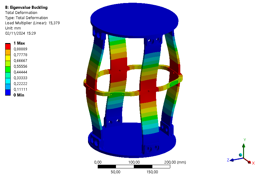
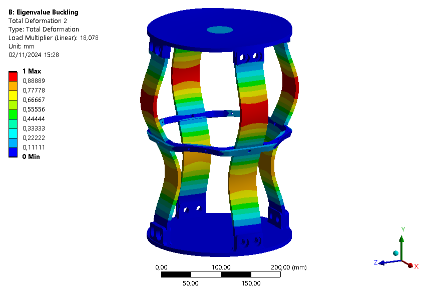
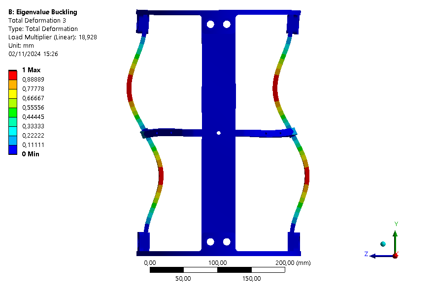
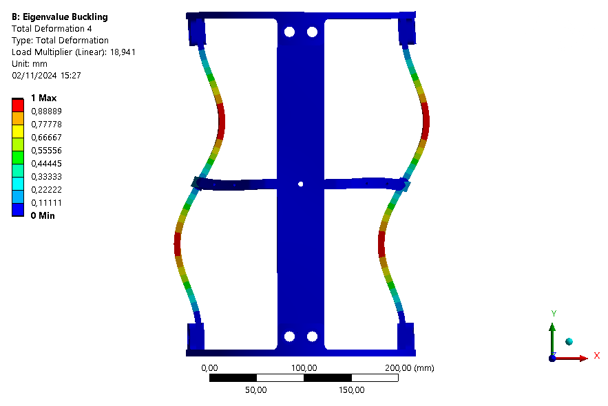
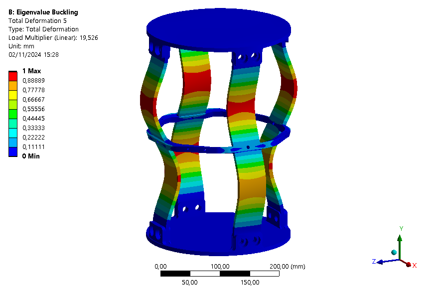
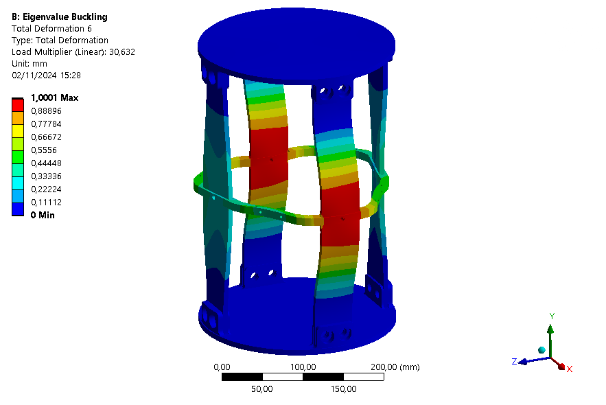
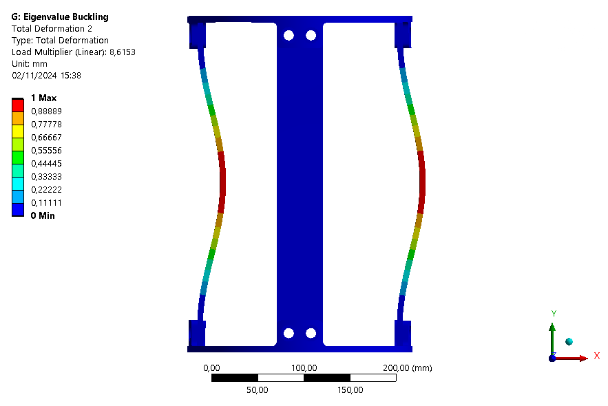
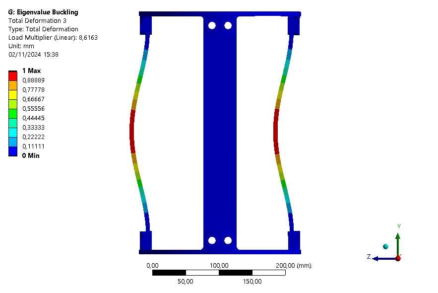
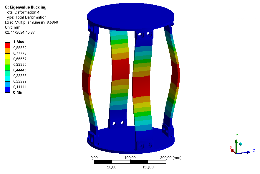
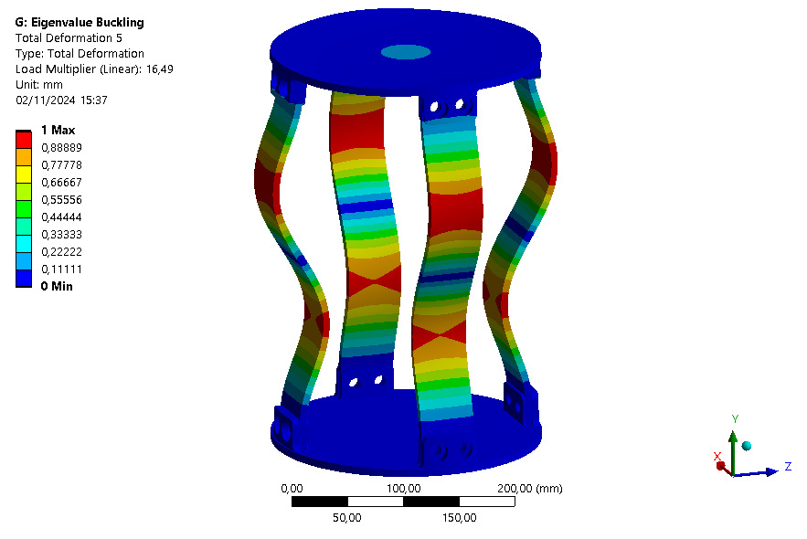
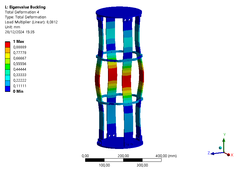
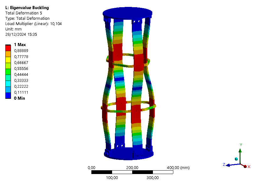
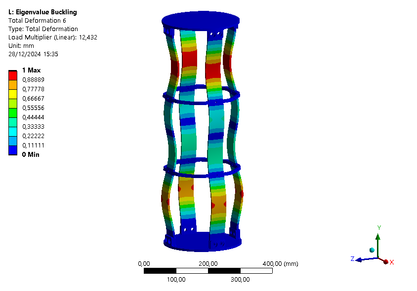
The six first buckling eigenmodes are extracted for an assembly with an ABR and one without it.
|:---:---:---:---:---:---:---
| Eigenmode | 1 | 2 | 3 | 4 | 5 | 6 |
| Loadfactor | 15.379 | 18.078 | 18.928 | 18.941 | 19.526 | 30.632 |
|:---:---:---:---:---:---:---
| Eigenmode | 1 | 2 | 3 | 4 | 5 | 6 |
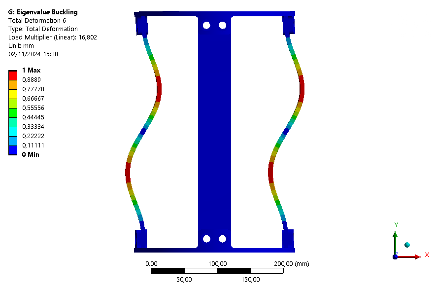
| Loadfactor | 8.4876 | 8.6153 | 8.6163 | 8.6368 | 16.49 | 16.802 |

|:---:---:---:---:---:---:---
| Eigenmode | 1 | 2 | 3 | 4 | 5 | 6 |
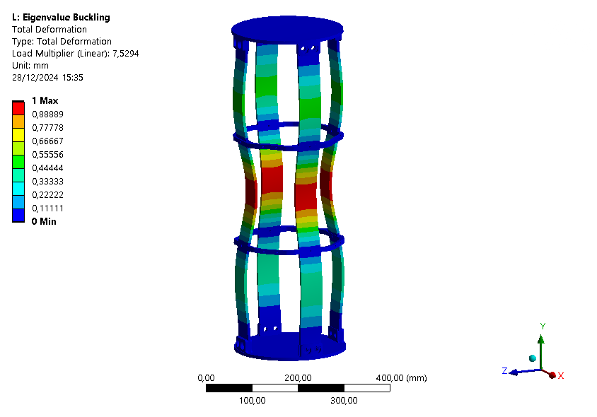
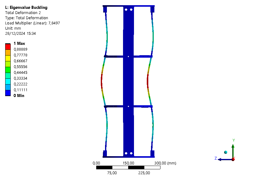
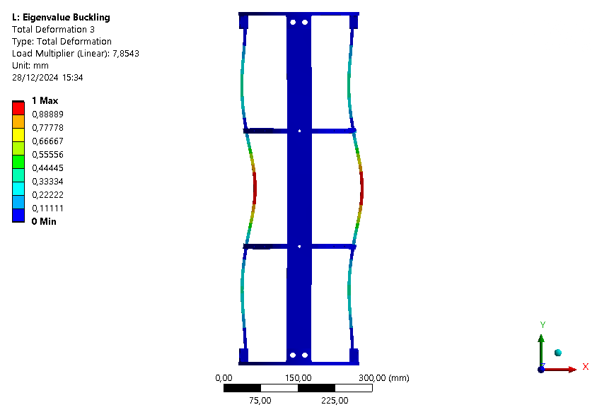
| Loadfactor | 7.5294 | 7.8497 | 7.8543 | 8.0812 | 10.104 | 12.432 |
¶ Interpretation
¶ Simulation validity
This simulation is only a linear buckling analysis, so the loadfactors are approximate and a non-linear buckling analysis is required to find more precise results. However, this gives us a good idea of how the module reacts to buckling by determining the first buckling modes.
¶ Conclusions
This buckling analysis of a module helps us to understand the behavior of the module under compression. It shows that the rods are the first parts to buckle as expected, and that the ABR fulfills its role by increasing the maximum load that can be applied on the module.
It is also interesting to note that with the ABR, the ABR is limiting element for buckling. Indeed, the first mode is a mode where the ABR buckles.
Also, since the loadfactor of the first eigenmode is around 8.5, it might be possible to have no ABR on this module.
To confront these results, a non-linear buckling analysis will be performed, as well as mechanical tests of the whole module.