¶ Goal(s) of the study
This study is in continuity with the linear buckling analysis carried out previously 2024_C_ST_MODULE_FEA.
The goal of this new analysis is to study more precisely the buckling behavior of a rocket module, trying to determine the critical load of the module using a non-linear analysis.
Indeed, a non-linear analysis takes into account all non-linearities directly linked to the buckling phenomenon, which allows for more precise results that are closer to what actually happens.
¶ Parts Involved
¶ Geometry
The geometry used here is the same as for the linear buckling analysis, i.e. two complete modules for avionics bay, with four CFRP rods, two couplers, one at each end, simplified for the tests (without the coupler interface) and zero or one ABR and a module of pressurant bay with longer CFRP rods and two ABRs.
To simplify the contacts, which can quickly be difficult to handle with simulations, the screws and bolts are removed. The goal of this study is the global behavior of the structure in buckling so it is possible to simplify the contacts in this way without loss of precision in the results.
¶ Function
This module, just like the others present in the rocket, must ensure structural integrity of the rocket and supports all loads applied to it.
¶ Material
The ABRs are in aluminum Al2050-T84 and both couplers are in Al6082-T6.
The rods are made of CFRP whose layup is described in 2024_C_ST_CFRP-PLATE_MAP.
¶ Load case
The module must withstand all the loads applied to the rocket. This analysis focuses on lift off, when the rocket is subjected to compressive forces and must resist buckling.
- 2024_C_SE_ST_REQ_31 Load Case - Axial compression
The structural load-bearing elements shall withstand axial compression loads of [15000]N. - 2024_C_SE_ST_REQ_37 Margins of safety for simulation validation
Unless specified otherwise, all parts shall be designed to withstand their design load with an additionnal Margin of Safety (relative to the elastic limit or other applicable failure criterion) depending on the part's nature: MoS 0.25 for all static simulations, MoS 3 for all buckling load cases, MoS 3 for all parts designed via generative algorithms.
¶ Finite Element Analysis
¶ Software
- ANSYS Mechanical
¶ Type of simulation
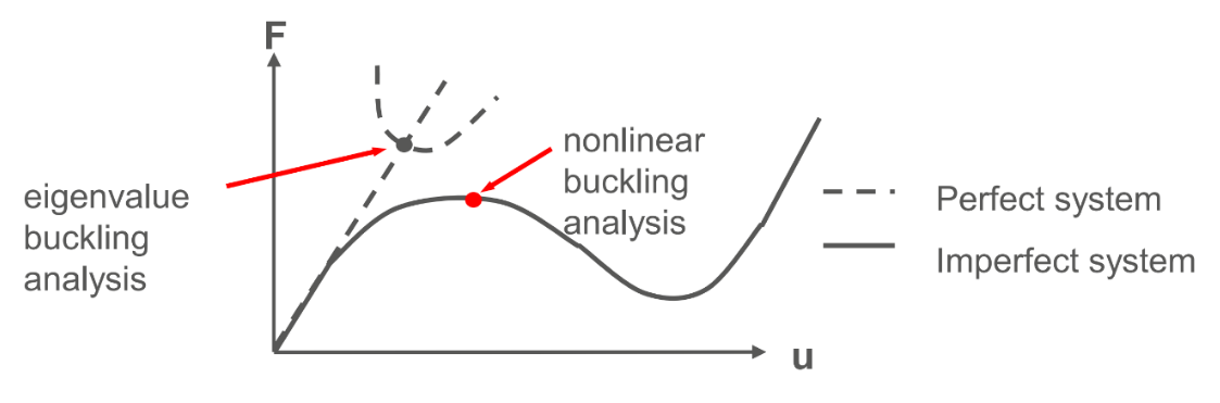
A non-linear buckling analysis is performed. This is usually done performing first an eigenvalue buckling analysis and using the first mode to induce a deformation to the structure. However, with this method it is not possible to change the orientation of the materials for the rods, which results in an incorrect setup for this simulation.
Instead, a static structural simulation is run and the instability leading to buckling will be introduced with small forces on the structure.
- Static structural
¶ Inputs
mmNS mm-ton-N-Nmm-MPa-mm^4-mJ
The couplers doesn't have the coupler interface, only a flat surface instead.
The screws and nuts are removed to simplify the contacts.
Otherwise, the geometries are kept as it is.
¶ Aluminum alloy 2050 T84 and Aluminium alloy 6082-T6
| Density (g/cm^3) | Young's Modulus (GPa) | Poisson's ratio |
|---|---|---|
| 2.7 | 76.5 | 0.33 |
¶ CFRP
The CFRP properties have been defined using ACP.
The properties for the UD and woven plies are:
| Material | Density (g/cm^3) |
|---|---|
| UD | 1.47 |
| Woven | 1.49 |
|||||||||||
| | Elastic (Engineering constants) |||||||||
| Material | E1 | E2 | E3 | Nu12 | Nu13 | Nu23 | G12 | G13 | G23 |
|---|---|---|---|---|---|---|---|---|
| UD | 137000 | 10500 | 10500 | 0.3 | 0.3 | 0.51 | 5200 | 5200 | 3476.82 |
| Woven | 49000 | 49000 | 10000 | 0.05 | 0.35 | 0.35 | 5000 | 4500 | 4500 |
In ACP, the layup from 2024_C_ST_CFRP-PLATE_MAP was defined, which gave the following properties for the CFRP rods using an orthotropic model:
| Density (g/cm^3) | E1 | E2 | E3 | Nu12 | Nu13 | Nu23 | G12 | G13 | G23 |
|---|---|---|---|---|---|---|---|---|
| 1.5 | 88074 | 17739 | 10000 | 0.3 | 0.3 | 0.3 | 3500 | 4081.6 | 3192.2 |
To correctly apply the material for the rods, a coordinate system is defined for each rod, with the X, Y and Z axis oriented so that the properties are in the same direction as for the actual rods.
To perform a non-linear buckling analysis, the simulation is not stationnary. The "quasi-static solution" option is turned on.
In order to reduce the computational time the simulation takes, the simulation is divided into two steps.
-
The firs step from 0[s] to 0.5[s] is linear since buckling didn't yet occur. A high number of substeps is therefore not required. After some tests, an initial and minimum number of substeps of 1 with a maximum number of substeps of 10 is enough.
-
The second step is from 0.5[s] to 1[s]. It is when buckling occurs so a high number of substeps is necessary to have precise results. An initial and minimum number of substeps of 15 with a maximum number of substeps of 150 turned out to be correct without the simulation taking too long.
One end of the module is fixed and a compression load is applied on the other end of the module. In order to calculate the load, we need an estimation of the critical load given by the linear buckling analysis 2024_C_ST_MODULE_FEA.
For AV Bay with one ABR, the first buckling load appears with a loadfactor of 15.379 for 15kN. To ensure buckling occurs during the simulation, the load applied is with a 20% increase from the estimated critical load estimated with the linear simulation.
The same is done for the other modules. We have:
| Module | AV Bay with ABR | AV Bay without ABR | Pressurant Bay |
| Force applied [kN] | 276.82 | 152.78 | 135.53 |
As explained above, for a non-linear simulation it is necessary to induce an instability. Here, it is done with small forces. The most convenient way for this analysis is by applying four forces on the ABR outwards. This ensures symmetry of the model. A magnitude of 0.1[N] for each force is enough to cause buckling.
Moreover, since we want a simulation as close as a compression test with a press, the displacements in the X-axis and Z-axis are fixed at the top of the module, where the compression force is applied.
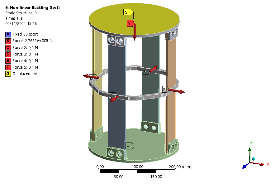
| Real case | Model |
| Attached to another module | Fixed |
| Compressed due to lift off | Compression force |
| Buckling | Disturbance forces |
Since buckling occurs when large deformations occur, it is important to activate "Large Deflection" and "Quasi-Static Solution" options.
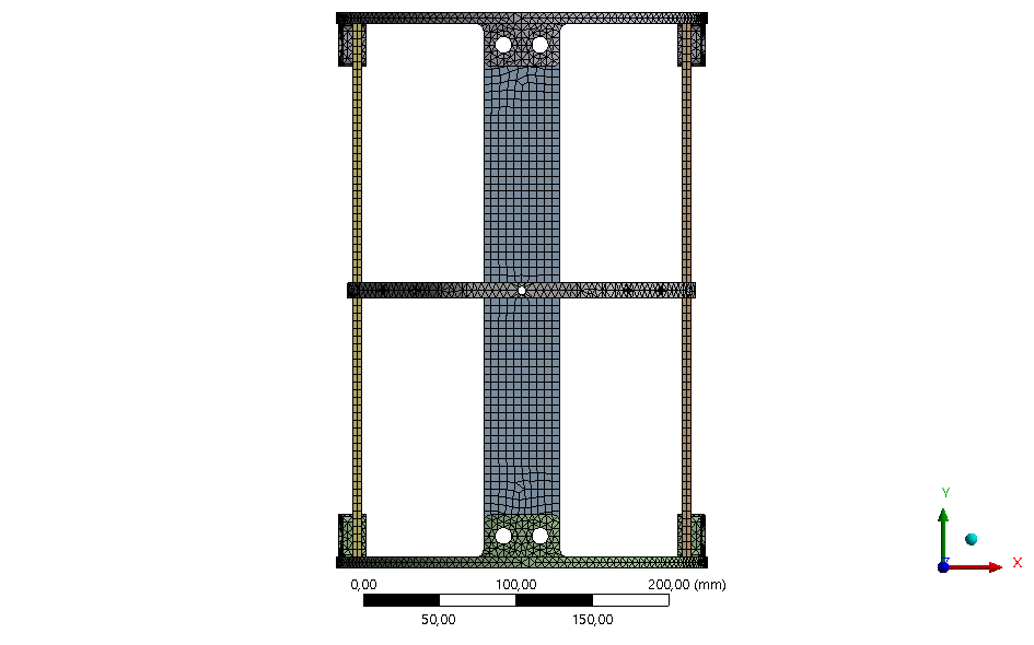
¶ Mesh
¶ Context
As a mesh convergence study has already been performed for the linear buckling analysis and the geometry is the same for both simulations, you can refer to this report for more details on the mesh used.
The same mesh can be used since the results are already mesh independent for the linear simulation. The mesh is then correct and we are sure to obtain accurate results without having to perform a new mesh convergence study. Moreover a non-linear buckling simulation is much more time-consuming and such a study would take an enormous amount of time to do and ultimately achieve the same results.
It is therefore advisable and usual to carry out the mesh study on the linear analysis.
¶ Final mesh used
The mesh convergence study showed that a global mesh of 5[mm] for the whole module gives overall good results. A smaller mesh won't be used here for time purposes. Indeed, by reducing the mesh, this will increase considerably the time the simulation can take.
¶ Outputs
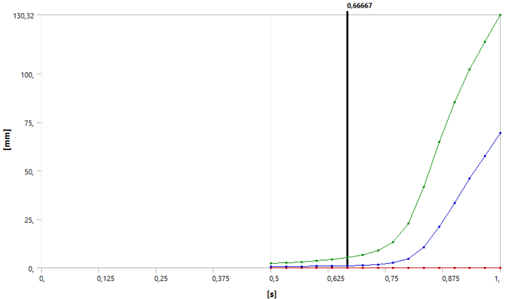
The only interesting parameter that can be extracted from a non-linear buckling analysis is the deformation as a function of time, and consequently as a function of the force applied.
The deformation plot as a function of time is the main results we have from this simulation.
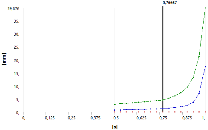
In this plot, we have:
- Red curve: minimum total deformation
- Blue curve: mean total deformation
- Green curve: maximum total deformation
There is no curve from 0[s] to 0.5[s] because, since this step is linear, the first substep calculated was at 0.5[s]. The deformation curve is linear in this first part.
After a certain time, buckling has occurred and the solver can no longer converge. This is what can be observed from about 0.9[s], where there are no more substeps calculated.
Looking at the force vs. displacement plot for buckling, we can define the moment buckling starts to occur as when the deformation is no longer linear with the load. Since in this simulation the force is applied linearly with time, this means that buckling occurs when the deformation is no longer linear with time.
This definition of buckling is conservative but since the carbon fibers cannot really buckle in reality and will most likely break before, it is a good assumption.
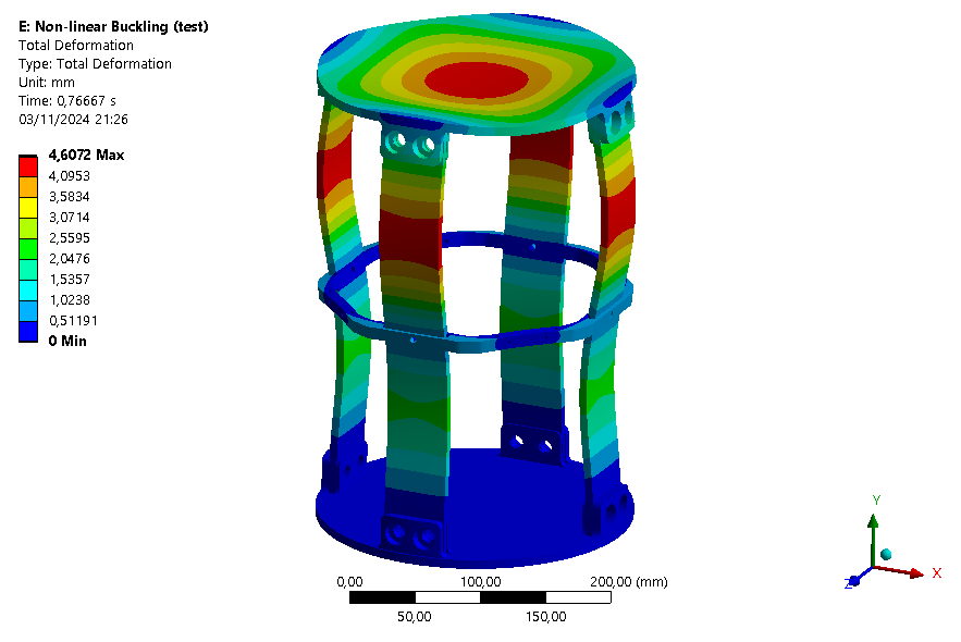
Looking at the plot, we see that the maximum total deformation is no longer linear from around 0.767[s]. We can estimate the critical load in buckling to be:
This gives a coefficient of safety of:
In comparison the one found with the linear buckling simulations is 15.38.
The deformation plot of the module at this time is shown below.
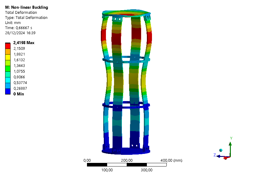
For the AV Bay without ABR, the deformation graph is given below:
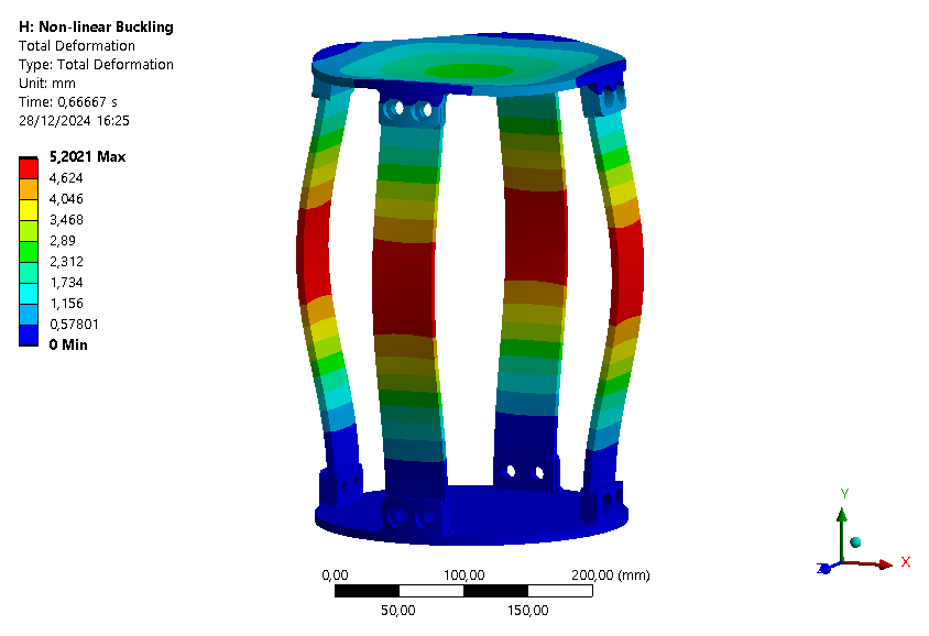
The deformation becomes non-linear starting 0.667[s]. The critical load is then:
This gives a coefficient of safety of:
In comparison the one found with the linear buckling simulations is 8.49.
The deformation plot of the module at this time is shown below.
For the pressurant bay, the deformation graph is given below:
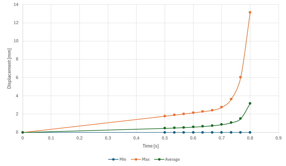
The deformation becomes non-linear starting 0.667[s]. The critical load is then:
This gives a coefficient of safety of:
In comparison the one found with the linear buckling simulations is 7.53.
The deformation plot of the module at this time is shown below.
¶ Simulation improvements
Thanks to the tensile test performed on samples from the CFRP plate produced for the rods, it has been observed that the actual Young's modulus in the principal direction of carbon is more around 74.861 [GPa] compared to the 88.074[GPa] given by Ansys ACP.
These simulations have therefore been modified with this new value for the Young's modulus, so that the results are closer to reality.
The new results are detailed in the following table.
| Module | AV Bay with ABR | AV Bay without ABR | Pressurant Bay |
|---|---|---|---|
| Critical load with Ansys' Young's modulus [kN] | 212.32 | 101.9 | 90.4 |
| Critical load with test's Young's modulus [kN] | 184.64 | 86.75 | 81.32 |
| COF with Ansys' Young's modulus | 14.15 | 6.79 | 6.0 |
| COF with test's Young's modulus | 12.31 | 5.78 | 5.42 |
¶ Interpretation
¶ Simulation validity
Even if some assumptions were made, this analysis gives the best estimation of the critical load for the different modules. This simulation is valid and the results can be used since a non-linear analysis gives more accurate estimation of the critical buckling load than with a linear buckling analysis. With the real value of the Young's modulus, the simulation is even more accurate.
¶ Conclusions
The loadfactors found with this simulation is lower than the ones found with the linear simulation. Consequently, the nonlinear analysis gave a lower critical buckling load as expected. These final values are the one to be used since this analysis is more precise and takes into account more parameters and mechanical phenomena.
This shows that the internal structure is well designed against buckling, meets the requirements and that an ABR is maybe not useful for this module.
These results will later be compared with a real destructive compression test of the module.