¶ Introduction
¶ Purpose, Objective and Scope
This document aims to list and analyze the results obtained during the tensile test of standardized CFRP samples, cut from the plate produced for the rods of the Firehorn I rocket.
It covers the results of the test and their analysis.
It does not cover the Test Specification and Procedure (TSP)
¶ Test Documentation
There are 3 main types of types of documents which relate to testing activities.
¶ AI&T
- High level overiew of testing activities
- Highlights dependancies in between types of tests
- Tracks the status of each type of test
- Document should be prepared as early as possible after PDR
¶ TSP
-
Test specification section explains:
- What part/assembly is being tested during each test.
- What characteristic is being tested.
- Brief description as to how the test is goind to be conducted.
- Explains the Pass/Fail criteria for each step.
- Explains when the test is due to happen and who will be involved in the test.
-
Document should be prepared after the baseline AI&T and ~1 month before the actual test.
-
Test procedure serves as a detailed plan for each individual test, it contains (among other things):
- A list of tools and instrument needed for the test.
- A description of the test location and condition.
- A step by step procedure of what needs to be done before, during and after the test.
-
Document should be prepared after the test specification and at least ~1 week before the actual test.
¶ TR
- The test report contains:
- The "as run procedure", meaning the procedure as planned ~1 week before the test with all of the comments and modiciations which were done the day of the test.
- The results of the test and all of the test data (or at least a link to the test data).
- If applicable, the analysis of the test data.
- The conclusion.
- The baseline document should be prepared the day of the test and the final version should be ready ~1 week after the test
¶ Definitions and Abbreviations
- ST : Structure
- FoS : Factor of Security
- ERT : EPFL Rocket Team
- TSP : Test Specification & Procedure
- CFRP : Carbon Fiber Reinforced Polymer
- GRP : Glass Reinforced Plastic
- FEA : Finite Elements Analysis
¶ Applicable and Reference Documents
- ASTM D3039 Tensile Tests
- 2024_C_ST_INTERNAL-STRUCTURE_DDF
- 2024_C_ST_ROD_FEA_2
- 2024_C_ST_CFRP-PLATE_MAP
- 2024_C_ST_TRACTION_ROD_TSP
¶ Requirements to be verified
- 2024_C_SE_ST_REQ_33 Load Case - Axial deceleration
The structural load-bearing elements shall withstand axial tension of [132000]N.
This requirement is for the whole structure. Since for each module there are 4 CFRP rods, the maximum load one rod must withstand is 33[kN]. Moreover, as the cross-section area of a sample is twice as small as that of a rod, the load the sample must withstand to have an equivalent tensile stress in the rod is 16.5[kN].
¶ As Run Test Procedure
 2024_C_ST_TRACTION_ROD_TSP
¶ Comments
During the tests, all the GRP tabs came off and the sample have slipped in the jaws. In order to have better precision, it will be necessary for next tests to find a more efficient way to glue the tabs on the CFRP samples.
¶ Test Report
¶ Test Data
All the data obtained with this test can be found on the EPFL Rocket Team Drive.
The file with the results of this test is called: "20241111_ASTM30391.xls"
¶ Test Results
¶ Data Analysis
For each sample, the tensile stress in [MPa] vs the deformation in [%] is given by the testing machine.
For the first test exclusively, we tried to load the sample until the machine's limit, up to 95[kN]. However we removed the extensometer at around the half of this load, so the deformation takes into account sliding in the jaws, not allowing usable results, but demonstrating that the rod can support at least a force of 95[kN]. The results for this first test are shown below.
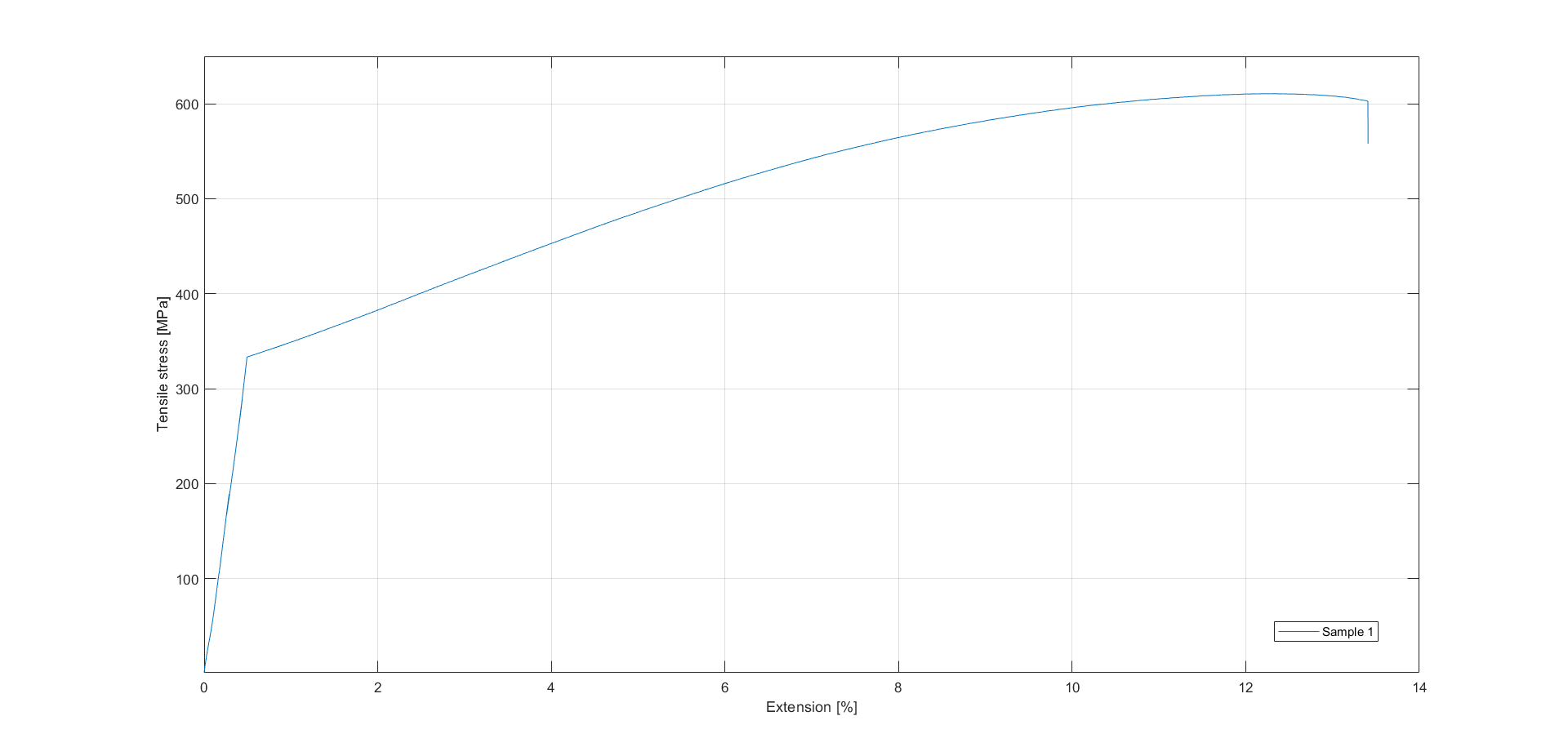
The abrupt change in slope in this graph occurs because of the removal of the extensometer.
For all the other samples, the maximum load applied is 50[kN], with the extensometer until the end of the test, allowing for more precise results. The results for these samples are shown below.
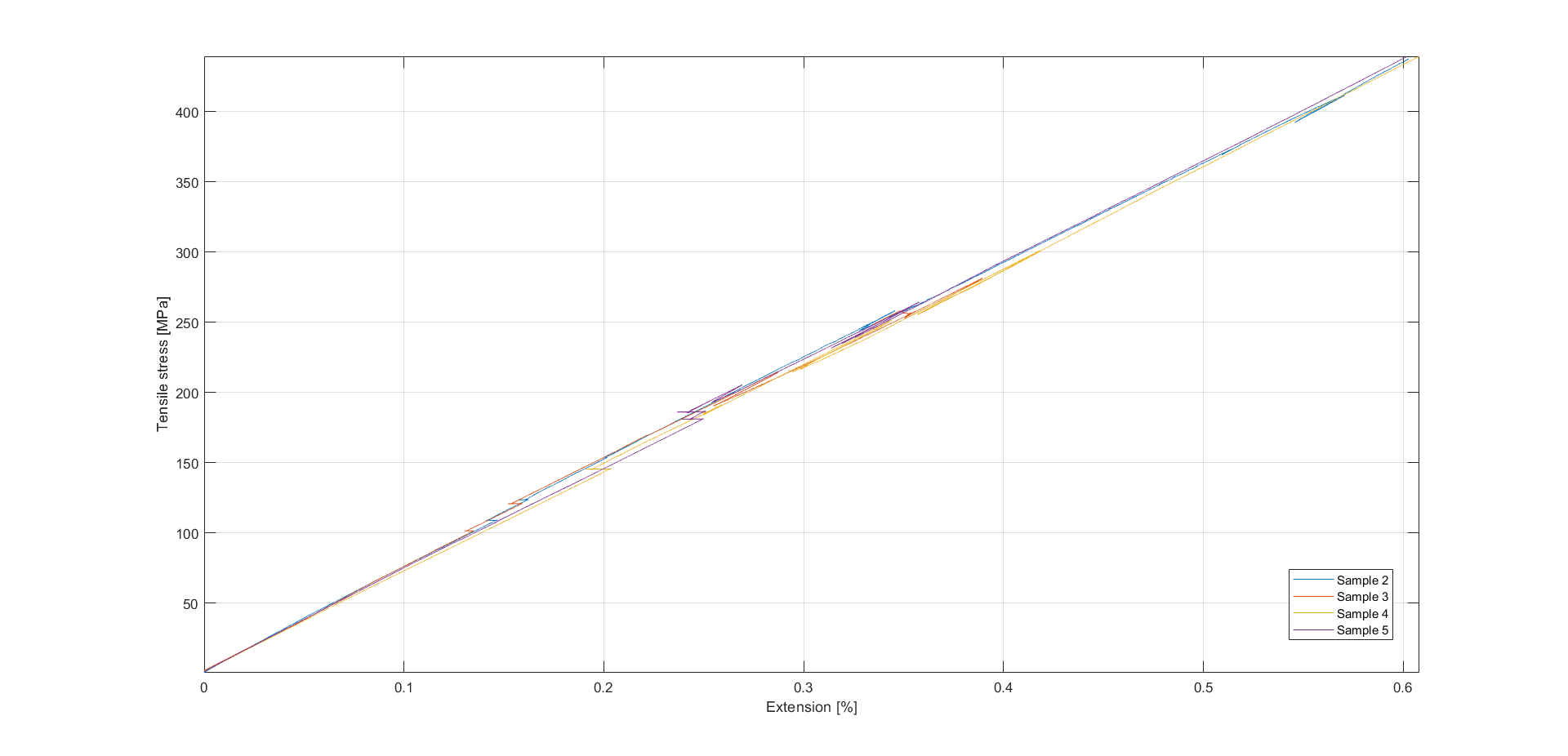
It can be observed that the curves are almost the same between the different samples, confirming the validity of these tests and showing little differences in CFRP performance depending on the location on the plate.
The small discontinuities in the results are due to slippage in the jaws, but have little impact on the results obtained here since the extension is given by the extensometer and therefore removes most of the effects produced on the results by these slips.
Finally, using the results from the last four samples (the results from the first sample cannot be used since they were not all measured with the extensometer), the Young's modulus of the CFRP plate can be estimated. The Young's modulus is directly estimated by the machine for each sample, and we can take the mean to have a final value.
| Sample # | Young's modulus [GPa] |
|---|---|
| 2 | 75.352 |
| 3 | 72.142 |
| 4 | 74.972 |
| 5 | 76.978 |
The mean Young's modulus is then 74.861 [GPa] for the CFRP plate in the main direction. The standard deviation is .
The Young's modulus estimated by Ansys ACP in the main direction is 88.074 [GPa], so it is actually much lower in reality compared to what was estimated. Therefore, it will be necessary to adapt the FEA simulations with this new Young's modulus value for the main direction.
¶ Pass Fail/Criteria
| Criteria | Pass/Fail ? |
|---|---|
| Resists a force of at least 16,5[kN] | Pass |
| Resists a force of 33[kN] | Pass |
| No cracks | Pass |
| The sample didn't slip inside the grips | Fail |
¶ Requirements which were verified
- 2024_C_SE_ST_REQ_33 Load Case - Axial deceleration
The structural load-bearing elements shall withstand axial tension of [132000]N.
This requirement is verified because each sample withstood much more than 16.5[kN], the force that gives an equivalent tensile stress as in an actual rod. The first sample supported 95[kN], the maximum possible with the machine, which is more than five times the requirement. Therefore this test is more than successful.
¶ Anomalies
The main issue with this test is the slippage of the samples in the jaws. It will be necessary for next tests to find a better way to glue the GRP tabs on the CFRP samples to avoid any slippage and further improve the accuracy of the results.