¶ Introduction
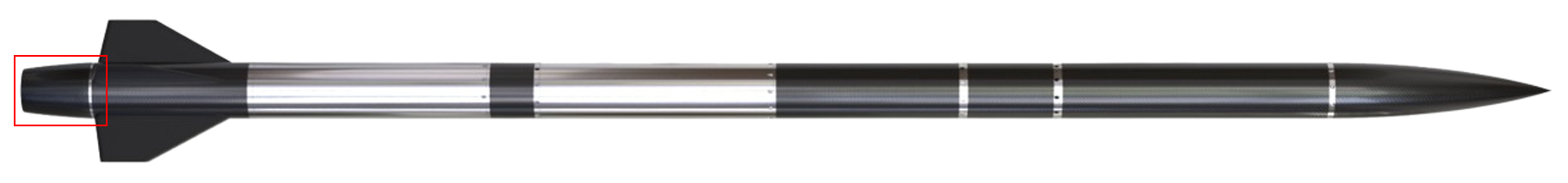
The Boattail is one of the main components of Engine Bay. Its primary objective is to streamline airflow and reduce drag at high speeds, thereby improving aerodynamic efficiency and stability during flight. One of its secondary goals is to protect the engine from sustaining any possible damages at touch down and, together with the Exhaust Shield, avoid any of the hot gases produced by the exhaust nozzle from re-entering the EB and damaging internal components.
¶ Definitions and Abbreviations
- EB: Engine Bay
- FT: Fixation Tree
- CFRP: Carbon-fiber-reinforced polymers
- DS-EB: Dual-Stage Engine Bay
- SS-EB: Single-Stage Engine Bay
- CNC : Computer Numerical Control
¶ Relevant Knowledge Needed
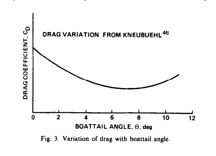
The optimal characteristics for the Boattail of a supersonic rocket are:
- (with the ideal value being to minimize drag
As of now, the current Boattail part is assumed to be a consumbale, which implies that for a nominal trajectory, it is expected to be changed after each flight due to possible damages caused during landing and exposure to high temperatures.
¶ Design Options
The Boattail has seen many iterrations in its materials, main ruling equation, length and thickness during its preliminary design conception, but at no point a decision between 2 designs had to be taken, as generally speaking, the next version, tended to be a direct evolution/improvement from the previous ones.
Despite the more chronological evolution of this part, we can clearly separate the Boattail into two main main designs that were adapted and engineered to offer optimal features for the two different configurations that the EB has experienced along its preliminary design process:
- The Boattail of DS-EB Boattail designs
- The Boattail of SS-EB Boattail designs
This design was initally meant to be fitted to an older version of the EB, which featured a now obsolete End_Ring very similar to the one in Nordend and an also obsolete Fixation_Ring which would serve as the fixation point from the Boattail to the End_Ring. It's main directing equation was a simple tangeant ogive, it featured a length of and a linear angle of .
Was designed to have the exact optimal characteristics as the length could be adapted within a certain limit to have the best .
Good ruling equation for subsonic, but not ideal for supersonic.
Due to the DS-EB design being quickly dropped early in the semester for the SS-EB to prioritize overall mass reduction, this design would have never been able to be implemented.
This second design of the Boattail is connected to the Thrust Plate via the Fixation Tree(s), which are 4 little bridge-like parts connected to both ends, which allow the Boattail to transfer part of its stress (in the case of a harder-than-expected landing) to the Thrust Plate which is specifically designed to hold larger than required axial loads.
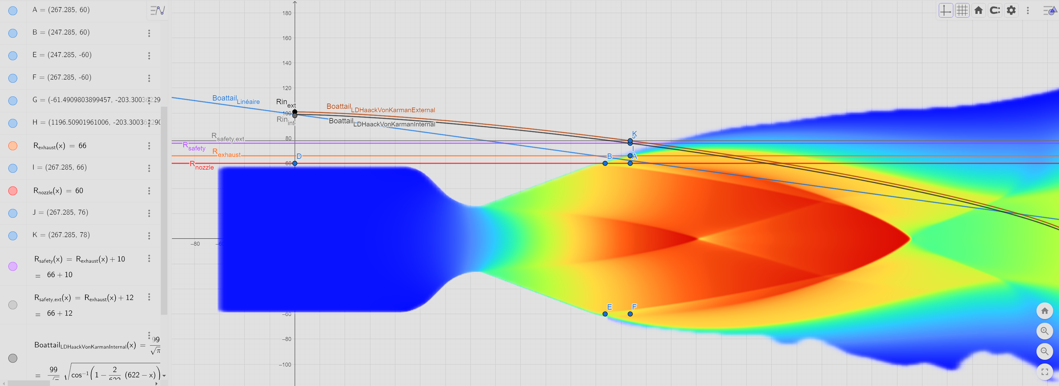
The length of this design in its latest iterration is which correspons to the x-intercept between an LD Sears-Haack Equation, with its parameters specific to the EB, the diameter of the exhaust Nozzle and the CFD predicted position of the exhaust flame at the boattail's end (with a 10mm radius additional safety margin).
Therefore, the length corresponds to and the linear angle is
Allows to be directly attached to the Thrust Plate via the Fixation_Trees which takes out the need for an End Ring (making the EB a lot lighter in the process).
The revolution of the main Boattail equation produces a Sears-Haack body which is the geometry that has the smallest drag coefficient at supersonic speeds.
The boattail parameters can not be within the optimal ranges described in the previously listed research papers, which means that the Boattail will not be perfectly optimised under this design.
Leads to a more complex manufacturability that either requires a custom CNC cutted foam mould (similar to the nosecone's manufacturing) or CFRP winding techniques that requires expensive machinery.
¶ Narrowing the Design Options
Due to the second design being a direct evolution of the first one, with additional features implememented as the requirements changed. There never was an actual point where we had to choose between these 2 designs and as mentioned in the Thrust Plates DJF, an executive decision to prioritize mass reduction and therefore rocket perfomance was chosen over ideal aerodynamical features.
¶ Requirements and Design Criteria
These are main requirements that motivated this change and guided us through the conception of the current version of the Boattail:
-
2024_C_SE_ST_ENGINE-BAY_REQ_05
Boattail length
The ENGB shall have a boattail length of [250][+/-20]mm -
2024_C_SE_ST_ENGINE-BAY_REQ_11
Engine bay structure mass
The total mass of the ENGB structure shall be [6000][+/-600]g. -
2024_C_SE_ST_ENGINE-BAY_REQ_13
Exhaust isolation
The ENGB structure shall isolate the engine exhaust from it's internals -
2024_C_SE_ST_ENGINE-BAY_REQ_15
Engine Shock Protection
The boattail shall protrude at least [20]mm rearwards of the engine nozzle's end
¶ Design Iterations
The main changes being the type of equation and parameters applied to design the revolution body of the Boattail, we can separate this part into 3 principal iterrations from the oldest to the most recent.
¶ Iterations
This iteration was mainly inspired by Nordend's Boattail design and was meant to be fitted to the prior DS-EB design. It was therefore quickly scrapped due to being obsolete and not being able to perform as well as the other versions for the dimensions required of the updated SS-EB design. It was originally meant to be made exclusively in aluminium sheet in order to simplify and render less expensive the manufacturing, but after a new requirement was established, demanding that the boattail be designed to absorb part of the eventual shock occurring when impacting the ground after descent, this option was also quickly dropped and more resistant and light-weight materials were researched to fit this criterion.
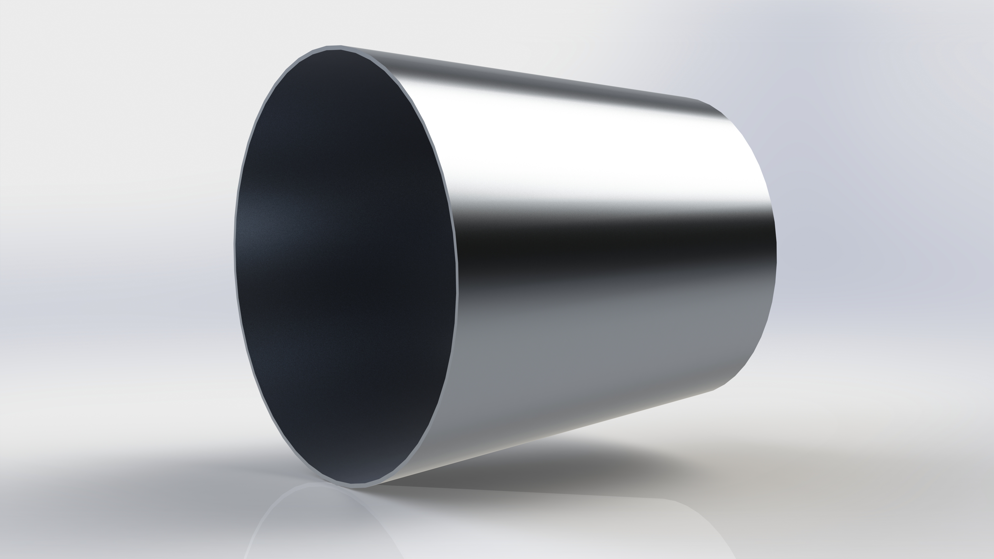
Very easy manufacturability.
Relatively inexpensive version.
Obsolete EB system.
Wasn't able to fit the new requirements without requiring a massive increase in thickness and thus in mass.
This iteration was also designed for the DS-EB design, but this time in the hopes of creating a more dynamically optimal boattail, that would lead to less drag at the rocket's end and better protection of the engine in case of impact. This design featured a tangent ogive as the main ruling equation and a complete CFRP structure either manufactured by prepeg layering to a mould or fliament winding. This iteration didn't stay for long either as it was adapted specifally for the DS-EB and a better version was designed by the time the SS-EB design was confirmed.
Better area than its previous iteration (but optimised for subsonic and not really for supersonic).
Was able to meet the new stiffness and length requirements for a more appopriate weight thanks to the use of CFRP as the main material.
Obsolete EB system.
Harder, more expensive and time consuming production.
The next version offering better aerodynamical properties was already in the making by the time the EB system changed
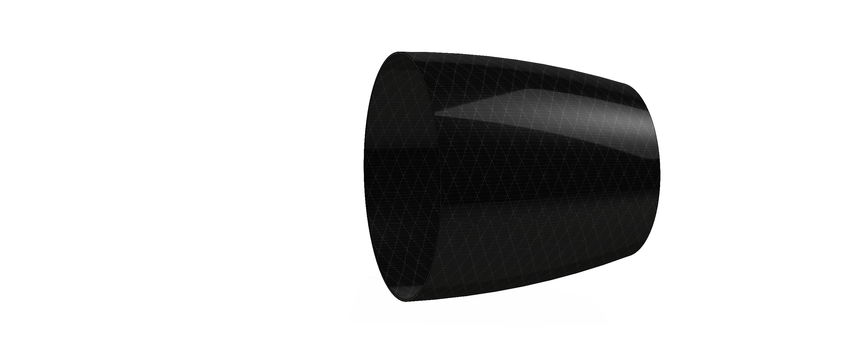
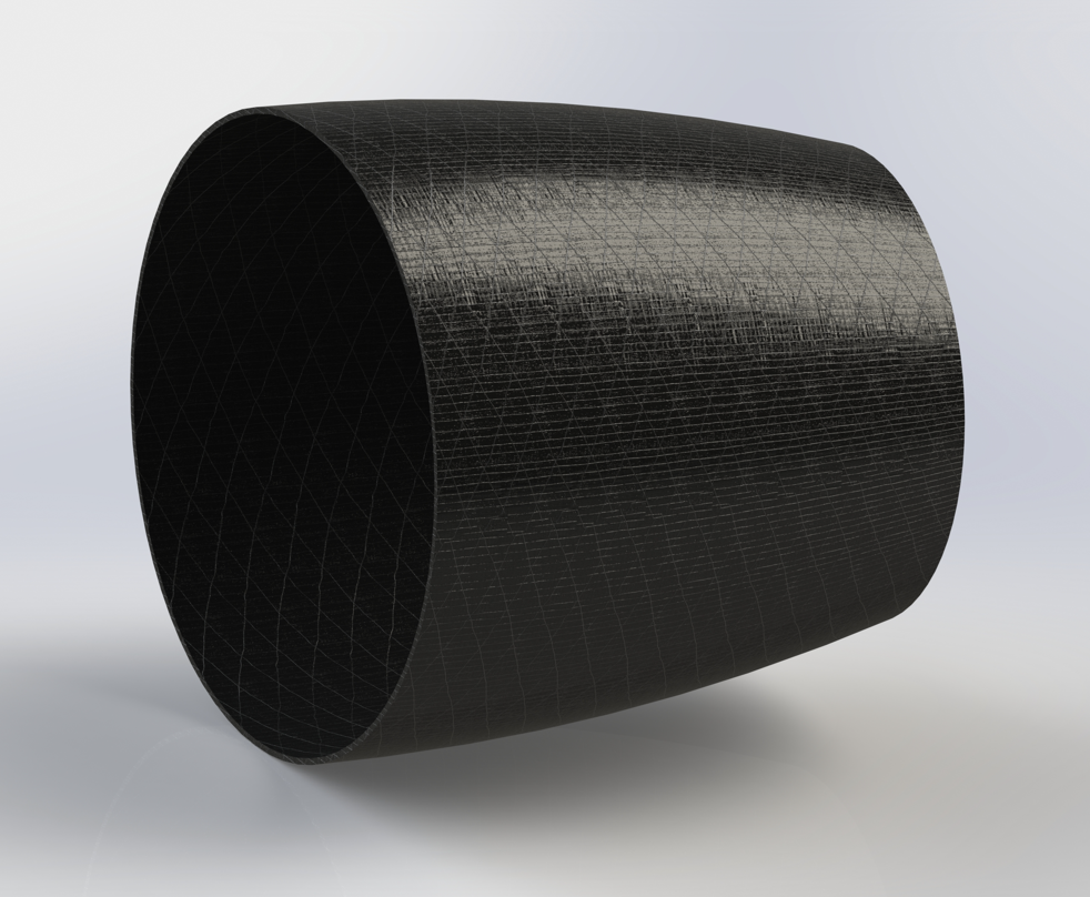
This iteration is the result of many upgrades on the previous versions regarding optimal thickness and attachement points to the rocket, the adjustment of the Boattail for way longer dimensions required by the new SS-EB design and the implementation of the sears-haack (also known as Haack's ogive) as the ruling equation of the Boattail.
This latter upgrade improved the dynamics of the Boattail by being "the best equation for both transonic and supersonic regimes" and thus optimize the most the drag produced by this part of the rocket, while at the same shaving a couple dozens of grams due to the total surface being smaller.
-
LD Sears-Haack type main ruling equation:
-
,
.jpg)
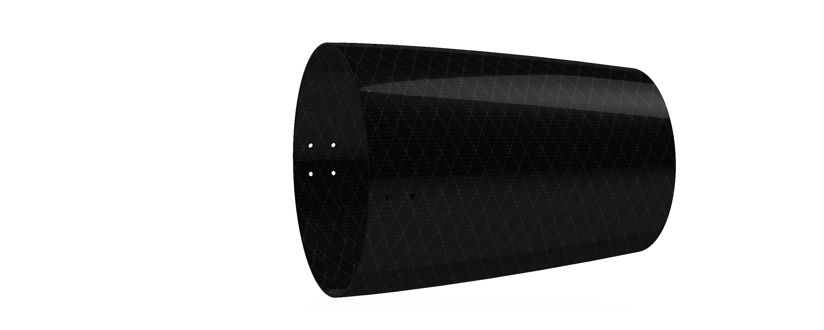
(Version with counterbore non-threaded holes that were meant to hide the protruding screws to improve the aerodynamics but were deemed very hard to manufacture and would not serve as good attachment points as they made easier the creation and propagation of cracks in the CFRP Boattail)
.jpg)
(Current version with simple non-threaded holes, fixed with rounded-head screws meant to perturbate the least the airflow around the boattail)
Better overall aerodynamical properties.
Lighter than the previous version.
Considerably harder, more expensive and time-consuming production.
Its properties are not quite in the optimal boattail length and inclination angle range, but close enough for it not to be a problem.
¶ Trade-off Results
Despite the LD-Haack boattail being a significant upgrade when it comes to reduce aerodynamic drag compared to the other options, because of the complexity of its geometry, it necessarily requires CFRP filament winding machinery to be produced and in the current stage of development we do not possess nor are in contact with a manufacturer with this sort of equipment. Therefore in the event that the situation doesn't change, it is likely that the boattail will be the linear design made of either aluminium sheet or multiple layers of prepeg.
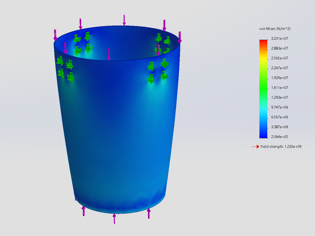
¶ Simulations
The main tests used to verify that the designs met the constraints and requirements were static load simulation but without the ability to define mesh direction and the specific fibres that will be used for manufacturing those still stay very approximative and require further fine-tuning.
In the future we would also like to implement "drop-test simulations" to have direct feedback on how well an eventual impact would be absorbed by the Boattail and if it would be able to withstand it without the engine being affected.