¶ Introduction
¶ Purpose, Objective and Scope
This document aims to describe the detailed manufacturing procedure of FIREHORN's nosecone.
It is addressed to the team members of C-ST and serves as a reference for the future CFRP nosocones.
The document will only cover the laminating part of the procedure. It will not describe the post-processing the nosecone.
Legends for highlighted text:
Function
Warning / Things to be careful of
Risks
Tips and Indications
Methods
¶ Definitions and Abbreviations
- C: Competition
- CFRP: Carbon Fibres Reinforced Polymers
- MS: Makerspace
- Prepreg: Pre-impregnated fibres
- ST: Structure team
- UD: Uni-directional
¶ Applicable and Reference Documents
- 2024_C_ST_NOSECONE-BAY_DJF
- Mould-Primer: XTEND® PR-ACP Mold Primer
- Mould-Release: XTEND® ACR-HS External Mold Release
- Woven: HexPly® F593
¶ Parts List
| Description | Part Ref | Qty |
|---|---|---|
| Nosecone | TX | 2 |
¶ Pre-Operations Checklist
¶ Participants
Number:
¶ On-site
| Check | Responsible for: | Name |
|---|---|---|
| COO | (x1) | |
| Cutter prepregs | (x1) | |
| Cutter consumables | (x1) | |
| Compactage/drappage | (x2) |
¶ Materials
¶ Makerspace / DLL
| Check | Item | Qty |
|---|---|---|
| Mould primer | 1 | |
| Mould release | 1 | |
| Bubble wrap (OBI) | \ | |
| Kevlar cord (malette RE DLL) | ~1m | |
| Mould | 2 | |
| Jig | 1 | |
| Thin cord 6m | 1 | |
| Chemical vapours mask | 2 | |
| Allen key set | 1 | |
| wide bodywork tape | 1 | |
| Pen/markers | 4 | |
| Alcohol | 1 | |
| Backup screws set for jig | 1 |
¶ APCO
| Check | Item | Qty |
|---|---|---|
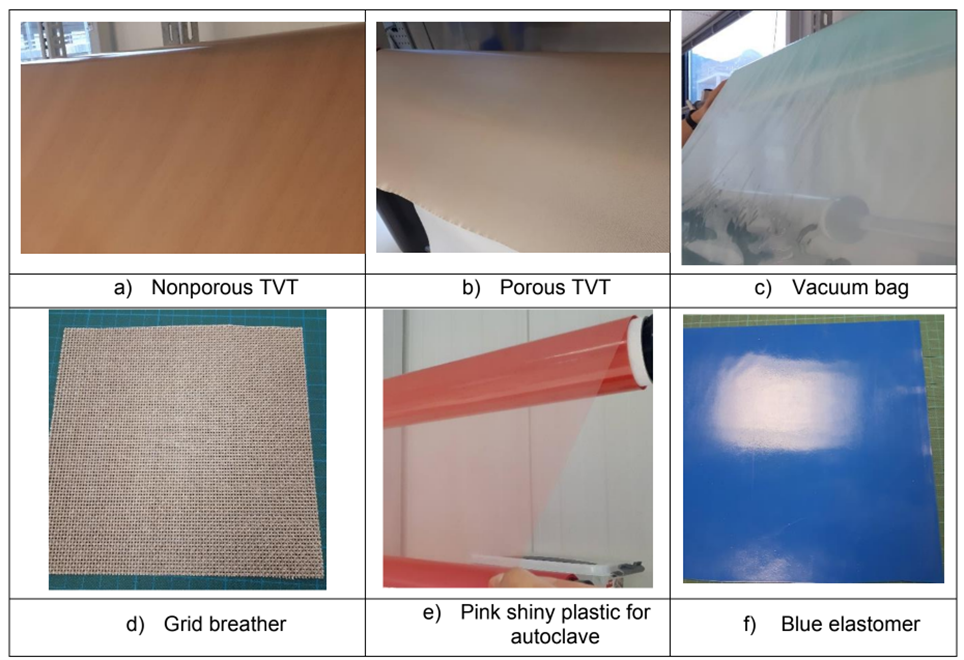
| HexPly®W3T-282-42’-F593-14 | \ | |
| Non-porous TVT / Peel-ply | \ | |
| Non-perforated film release | \ | |
| Breather | \ | |
| Grid breather | \ | |
| Vacuum bag | \ | |
| Elastomer | \ | |
| Nitrile gloves | \ | |
| Measuring tools | \ | |
| weights | \ | |
| Freeze spay | \ | |
| PTFE tape | \ | |
| Tacky tape | \ | |
| Vacuum connectors | \ |
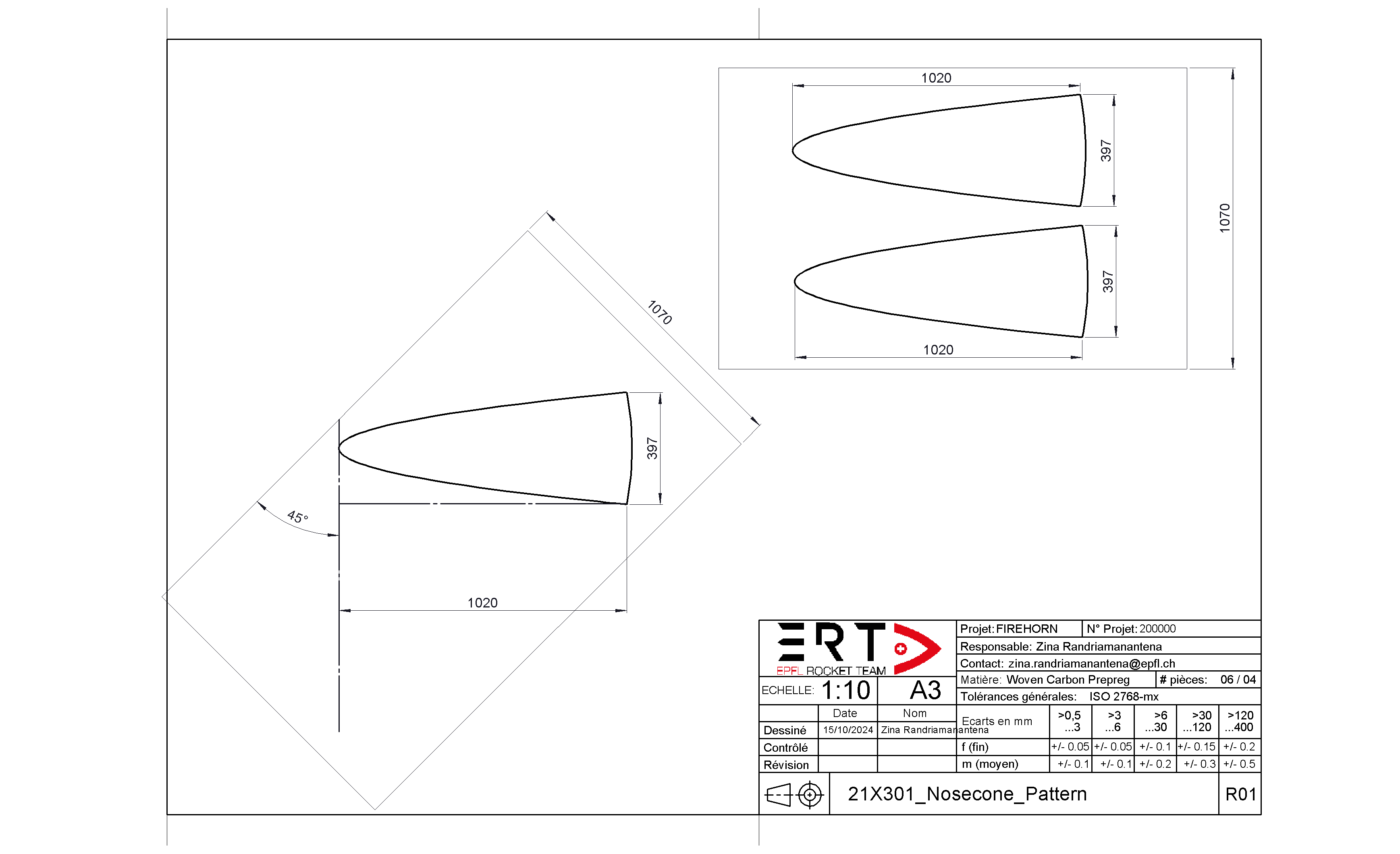
¶ Technical drawings
¶ Workflow
¶ Mould Preparation
¶ Off-site (Makerspace)
¶ Mould primer
To seal micro-porosities
- Wipe-On mould primer:
Use a clean lint free cloth or paper towel, wipe on in a straight line overlapping between applied edges.- Leave On mould primer for [min]:
The surface should be completely dry and tack free
before applying additional coats.- Repeat steps 1&2 five times.
- [h] curing at T_
Ensure to change cloth each coat.
A total of 6 coating layers are necessary
¶ Mould release
To make give high slip, high gloss surface finish
- Wipe-On mould release:
Wet the paper towel with XTEND ACR-HS until it is wet but not dripping. Gently squeeze the towel into a ball to soak the AXEL XTEND ACR-HS throughout the towel. Wipe on to the mold surface using smooth even strokes. Apply a thin, uniform coating and allow the release agent to evaporate.- Wipe-Off mould release:
Using a clean cloth lightly wipe over the surface removing any excess release agent- [min] waiting.
- Repeat steps 1-3 four times.
- [min] curing at T_
A total of 5 coating layers are necessary
¶ MDF Caps
- Draw a rosette on the screwed caps with clear indication of .
- Draw sectors at \
These are references for the lay-up application
¶ On-site (APCO)
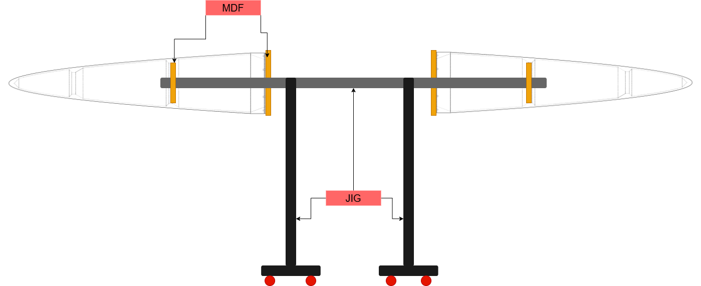
- Fix the MDF caps to the moulds.
- Mount the moulds on the trolley jig.
- Clean the surface using directly a mould release.
- Wipe-Off mould using clean cloth.
- [min] waiting.
- Tape blue PTFE on the cylindical part to fill the gap caused by 3D-printing default.
- Tape blue PTFE between bumps to fill the gap caused by 3D-printing default.
¶ Prepregs cutting
¶ Tip version
¶ 0deg
- Lay a pattern on the prepreg roll.
- Align the pattern symmetry axis with the fibres.
- Cut around the pattern.
¶ 45deg
- Draw 45° lines on the prepreg roll.
- Draw a line normal to the previous one.
- Lay a pattern on the prepreg roll.
- Put the tip of the pattern on the 45° line and put the lower point on the normal line.
- Cut around the pattern.
¶ Lay-up
- The operator must sign each time a ply is layed-up
- The COO have to verify that intermediate vacuuming has been done before allowing the application of next ply
Do not forget to remove patchworking tape
Place a piece of paper next to the plate on which is written the layer number, the fiber orientation and the intermediate vacuum. Be flexible when it comes to intermediate vacuum. If the layer has not been perfectly draped and you have a few bubbles, or if the layer does not adhere well to the underlay, make an intermediate vacuum even if it is not written on the control sheet.
| n° | Type | Orientation [°] | Operator | Check |
|---|---|---|---|---|
| 1 | Woven | 0 | ||
| Vaccum | 10 [min] | |||
| 2 | Woven | 45 | ||
| Vaccum | 10 [min] | |||
| 3 | Woven | 0 | ||
| Vaccum | 10 [min] | |||
| 4 | Woven | 45 | ||
| Vaccum | 10 [min] | |||
| 5 | Woven | 0 | ||
| Vaccum | 10 [min] |
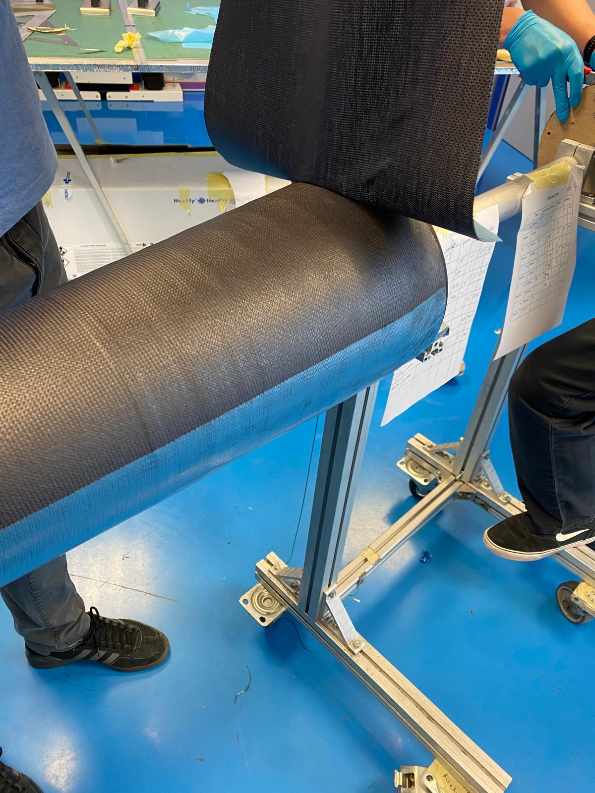
¶ How to apply prepreg ?
Number of operators needed per mould: 2 (3 for the 6th step)
- Mark the center the bottom side of the prepreg (wider side) with a marker.
- Align the bottom center with the needed orientation on the mould.
- Align the tip center of the prepreg on the mould (without sticking it to the mould).
- Be sure, when doing the second half, that the prepregs overlap on both sides.
- Begin sticking the bottom center of the prepreg to the mould.
- Apply a little bit of tension to both sides of the prepreg.
- 3rd operator follows the center line of the prepreg with it's fingers to slowly stick the center line of the prepreg to the mould.
- Apply the prepreg to the mould by gently massaging the fiber for it to take its final shape (begin at center line and slowly go to the edges) (apply tension and the heat of your hands if needed).
- Take your time and be patient, the first layer is especially difficult to apply because of the non-sticky nature of the mould.
- If second half applied, pull the vacum with grid breather around the nosecone.
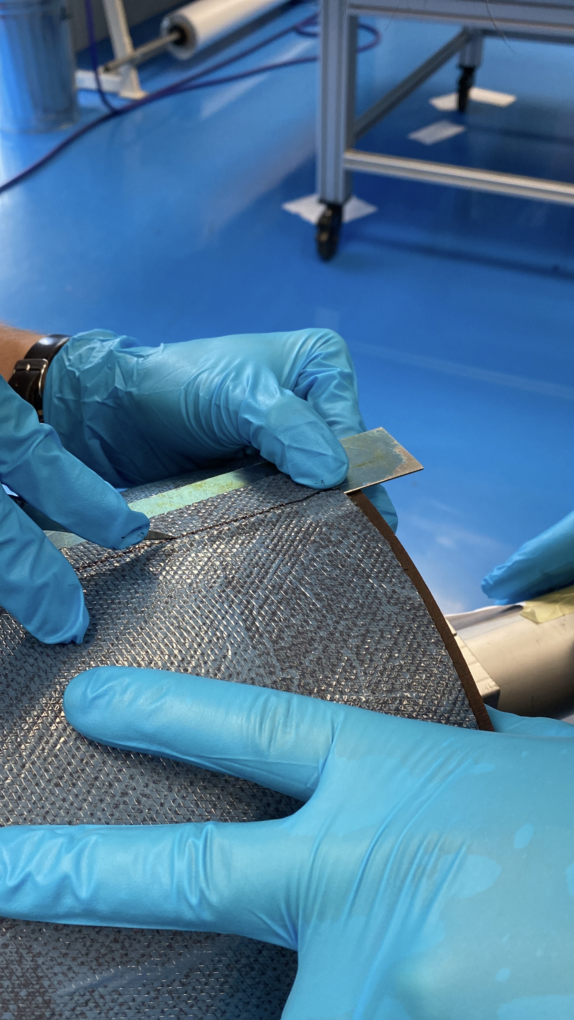
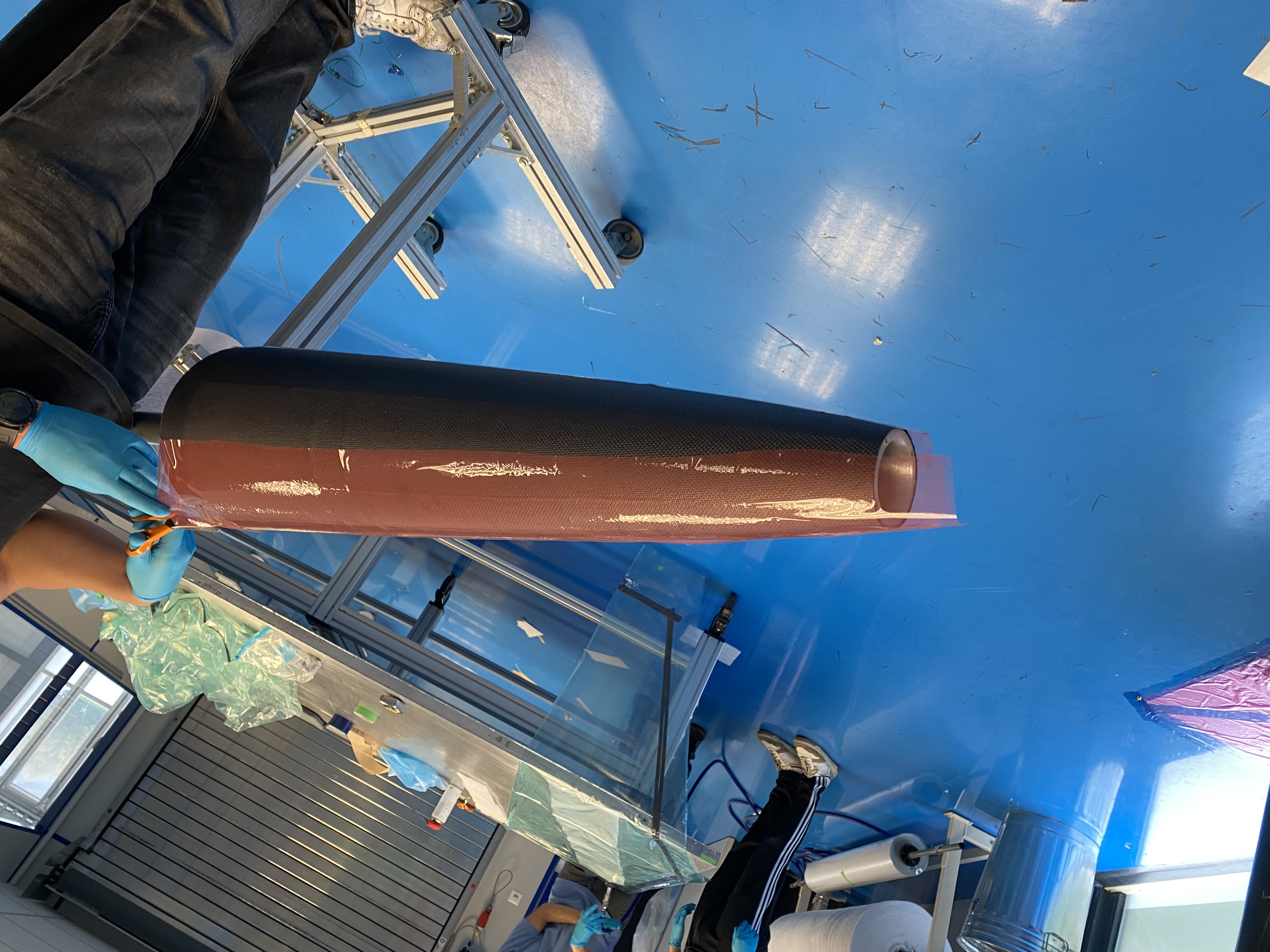
- Cut the excess material off (overlap) by:
- Marking the overlaping part with a marker, you can see a little bump on the material by playing with the surrounding light and changing your angle of view.
- Appling cold spray to the edges to fold up the overlaping part (you can pull with a lot of strength, because this part will be cut away anyways).
- Folding up the material untill you can see around 5mm of the exposed carbon fiber
- Puting a 1m ruler under the overlap and lightly stick the exess material to the ruler.
- With a scalpel, following the previously drawn line (go large, we do not want gaps).
- Removing the ruler, lightly stick the material back on the mould and see for remaining overlaps.
- Repeating untill the overlap is <1mm (this can take a lot of time, if you want a good result, go slowly and be patient).
For the pointy noecone, be prepared to put little cuts in the tip of the prepreg, because it is impossible to apply it onto the mould without folds otherwhise.
 |
.jpeg) |
|---|
 |
 |
|---|
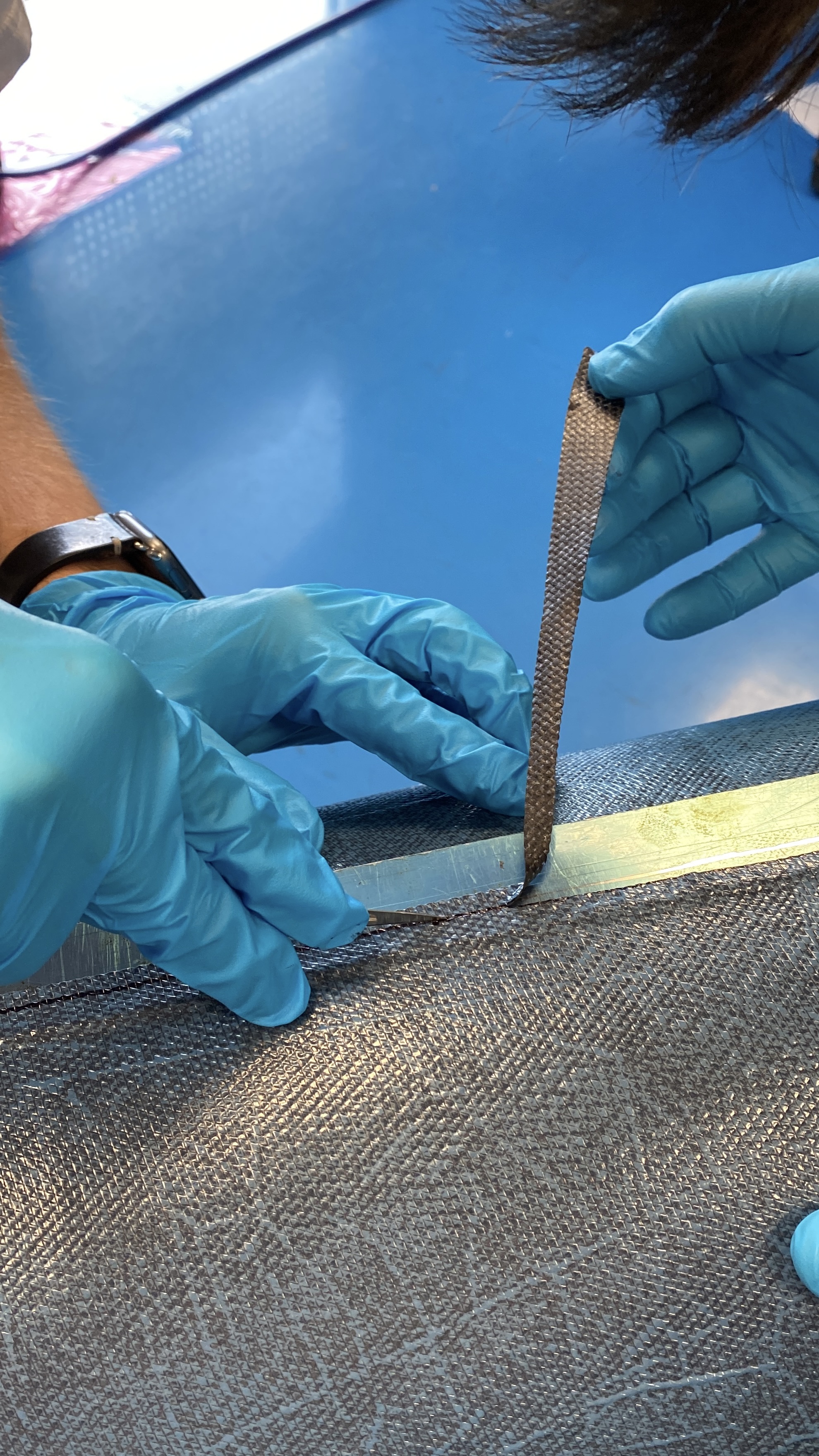
In the case of a gap:
- Cut a strip the same size as the gap and the same orientation as the layer.
- Apply the strip to the gap. Do not create an overlap with the strip.
¶ How to Intermediate vacuum ?
Number of operators needed per mould: 2
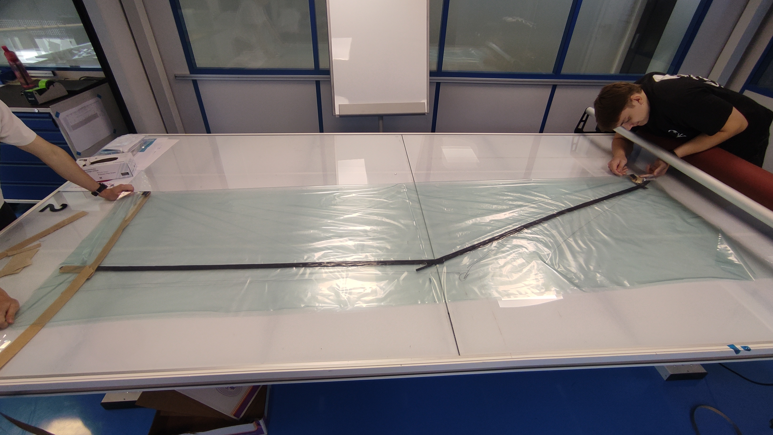
¶ Vacuum bags
- Cut a sheet of vacuum bag of size 2800x1600mm.
- Draw the fllowing shape with:
A = 700mm
B = 1300mm
D = 200mm
E = 30mm
F = 100mm
(All these values do not have to be exact, you can draw it approximately to save time)
- Put tacky tape on A,B,C,D and E
- Fold the vacuum bag around the center line (dotted line), and seel B,C,D and E(above D), leave A opened.
- At this point, you can test the vacuum by putting a valve in the A-B conner.
The vaccum bag should look like this:
- Cut off the excess platic
¶ Vacuuming
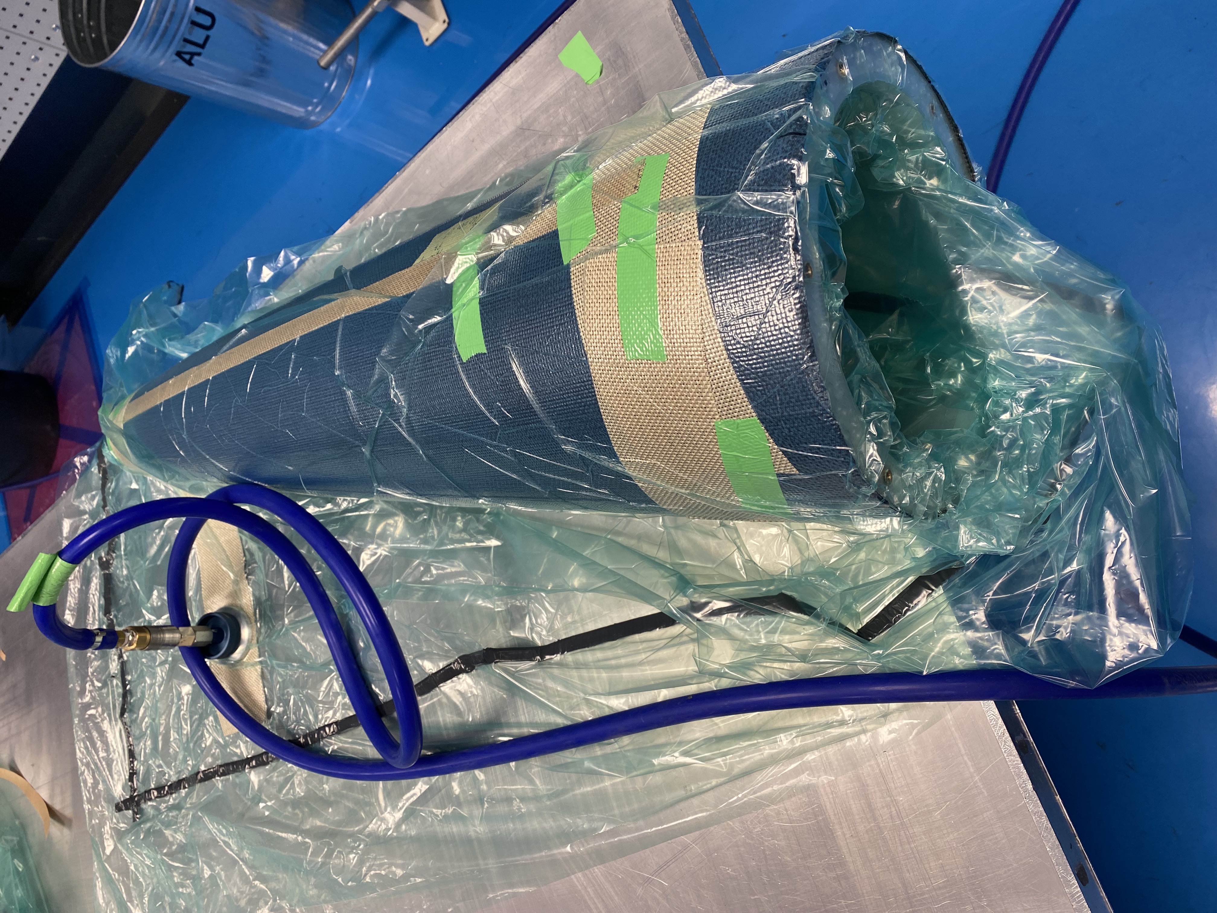
- Put Grid Breather around the nosecone according to the following picture by using green tape:
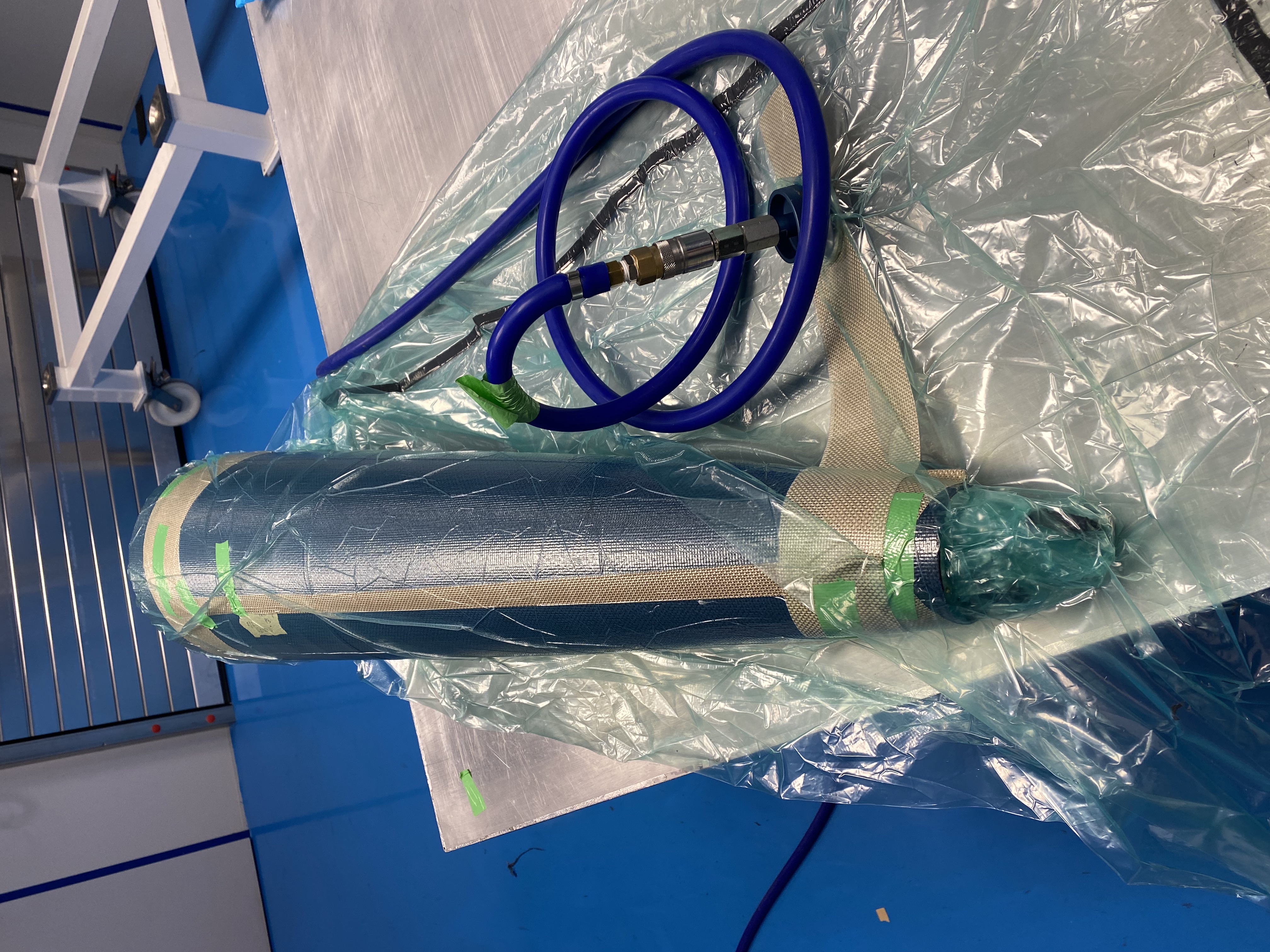
- Invert vacuum bag on itself (just like a sock).
- Insert the tip of the bag into the nosecone by using either a person with very long arms or a stick with a soft tip. (for the non-pointy nosecone, pull the end of the bag through the hole to insure that it does not pop)
- Wrap the rest of the bag around the nosecone (by inverting it again).
- Align the valve with the extended breather part.
- Secure the breather with green PTFE tape.
- Carrefully seel the vacuum bag, pull vacuum and check for leeks.
¶ Final vacuum
- Remove the protective film from the last layer.
- Cut film realease into Pregreg shaped patterns.
- Cut the shape in halve along the center-line.
- Apply the film release just like the Prepreg onto the mould.
- Make the 4 overlaps the same size and symertical to each othe for it to look nice after demould.
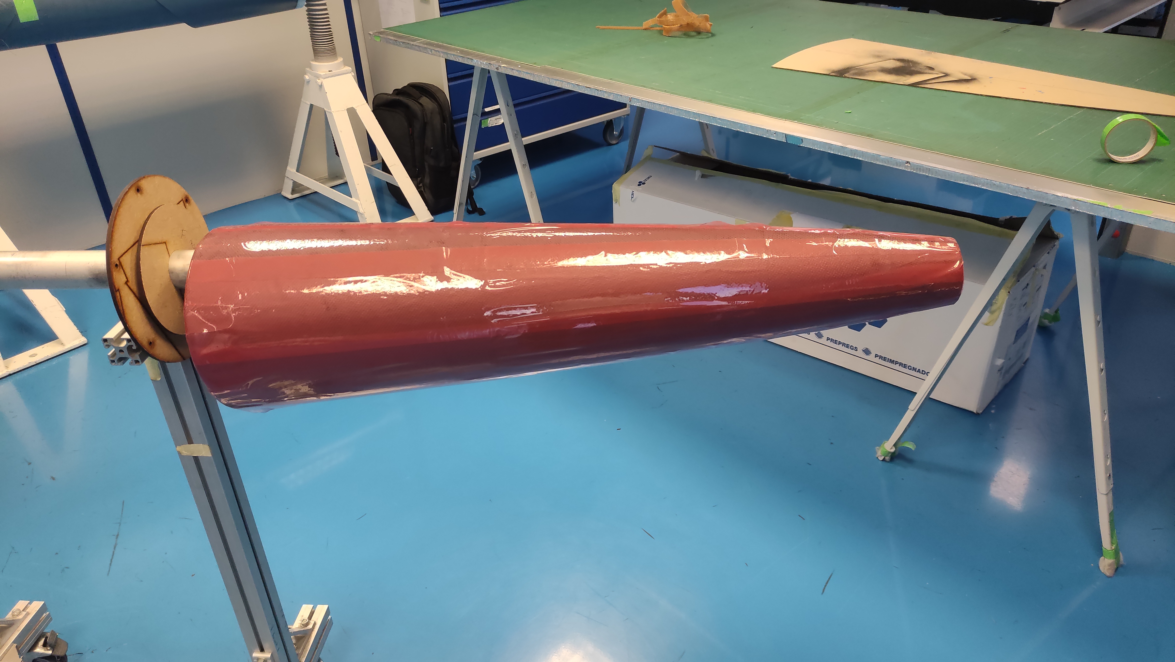
- Tape the ends to the inner-side of the mould with green tape
- Repeat until you obtain 3 layers.
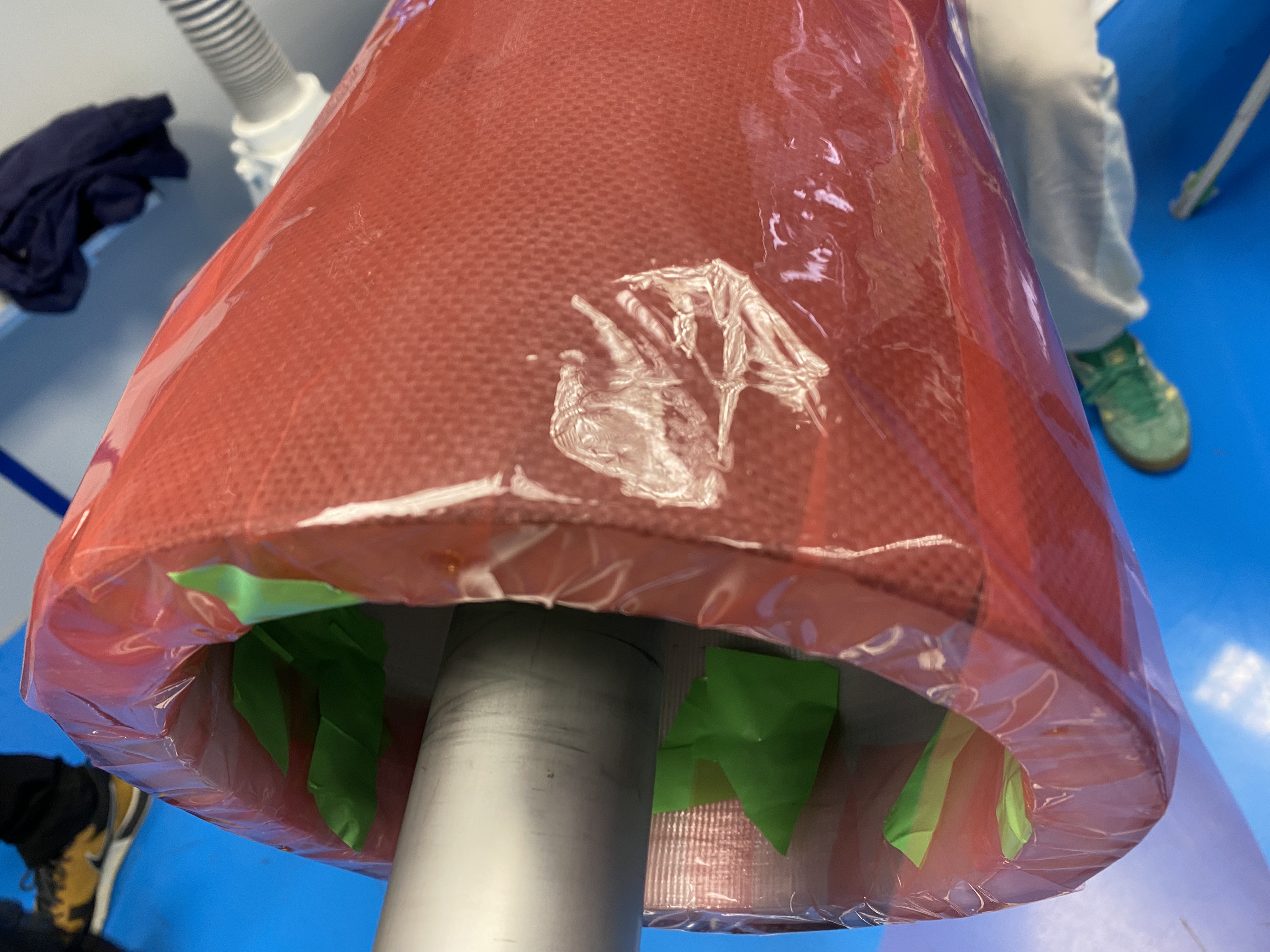
Any wrinkles on the film will show on the tube
- Cut non-porous TVT just like the film release.
- Apply the non-porous TVT just like the film release
- Cut two Prepreg shaped sheets of non-pourous TVT (do not cut them in halve) and apply them to the mould.
- Wrap breather around the nosecone and tightend it with tape.
- Repeat normal vacuum procedure, but with a vacuum bag that is secured with twice the amount of tacky-tape.
Do final vacuum test before autoclave for an extended period to insure that the bag is leek-proof.
Also try to avoid any wrinkles on the vacuum bag to insure distributed forces.
¶ Curing cycle
- Time at 100 [°C]: 420 [min] 7 [h]
- Heat the part to 100 [°C] with speed of 2 [°C.min−1]
- Keep it at 100 [°C] for 420 [min]
- Cool the part to 20 [°C] with speed of 2 [°C.min−1]
- Freeze the mould to allow it to contract.
- Demoulding
¶ Post-curing
- Time: 310 [min] 5 [h] 10 [min]
- Heat the part to 100 [°C] with a speed of 2 [°C.min−1]
- Keep it at 100 [°C] for 30 [min]
- Heat the part to 180 [°C] with speed of 2 [°C.min−1]
- Keep it at 180 [°C] for 120 [min]
- Cool the part to 20 [°C] with speed of 2 [°C.min−1]
¶ Post Conditions
| Check | Step | Description | Image |
|---|---|---|---|
| 1 | Check for wrinklings | ||
| 2 | Check for cracks | ||
| 3 | Check the inner surface | ||
| 4 | Do some dimension checks |
- Theoretical thickness = 1.2 [mm]
¶ General Comments
¶ Bumps on the mould
There might be defaults on 3D-printing that may cause problem on demoulding. In fact, when there is a change in radius or at the edge of a cynlindrical form, bumps can form. They are probably caused by filament contraction during solidification.
The CTE of the PETG is ranging from to [µm/(m.K)]. In comparison aluminium has a CTE of about [µm/(m.K)].
- The CFRP tube was demoulded easily with just mould release and thermal contraction at room temperature.
- With that in considerations, no significant measure is adopted to mitigate the potential demoulding issue. The gap between bumps will be just filled by PTFE tape.
¶ Cutting pattern considerations
¶ Solidworks surface flattening
Solidworks allows to flatten any surface using the function Flatten Surface, which an approximation using finite elements method.
|:----
| 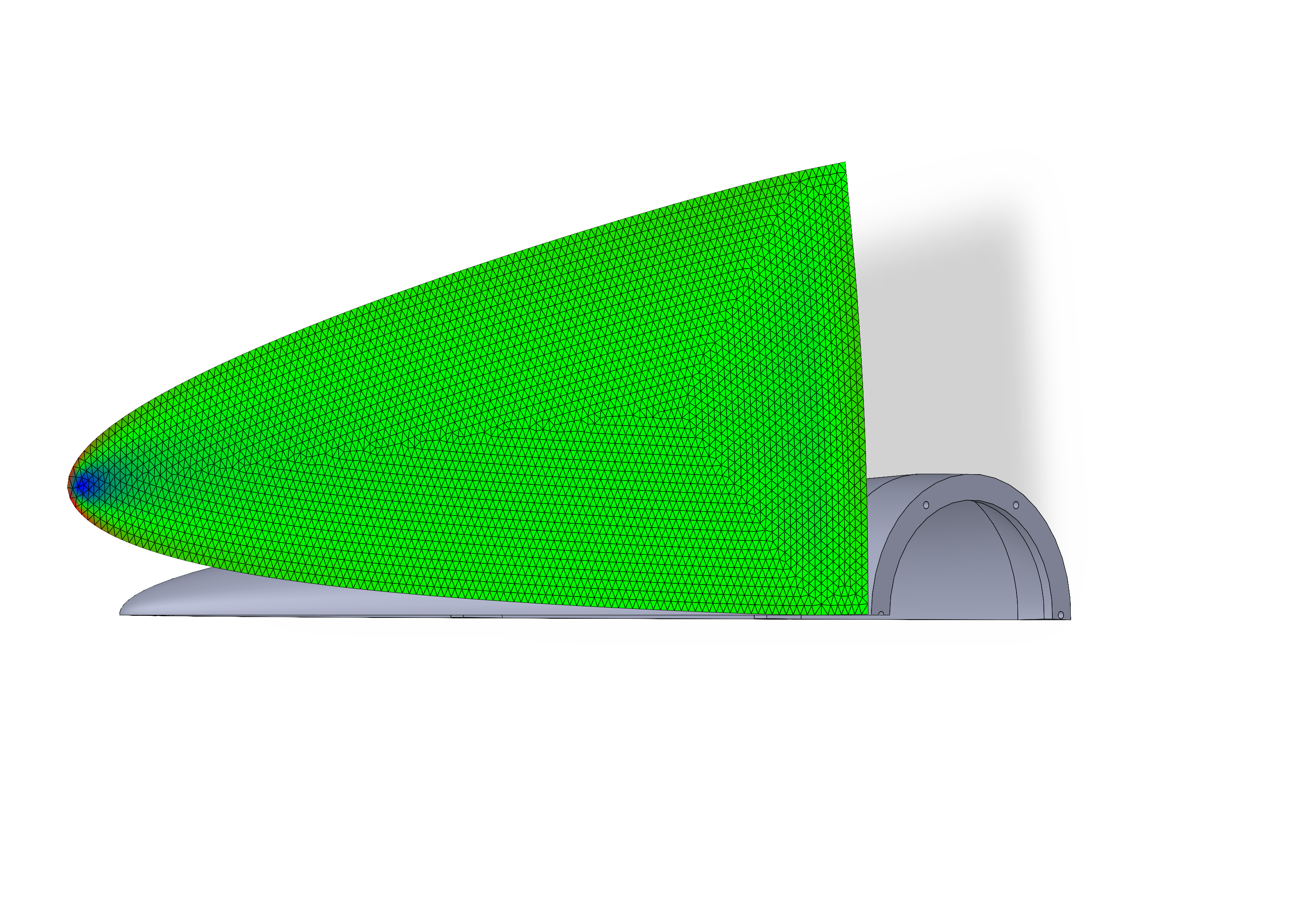 |
|
| Surface flattening (red: stretching ; blue: contraction ; green: no distorsion) |
¶ Surface flattening equation
The profile of the nosecone mould is given by the following equation:
- [mm]
- [mm]
So, the (partial) circumference at every point is given by:
with, the angle of revolution around the main axis. There is a factor because the flattened surface is constructed by mirror symmetry of the curve .
The geometry is closed by an arc, with a center at the tip, connecting two mirrored curves.
¶ Real case
¶ Body
As the stretchability of the prepreg is unknown, [rad] to allow resizing cut when applying the ply.
In order to include the cylindrical part, the is evaluated from the tip to the basis of the whole geometry.
- [mm]
- [mm]
- [rad]
- [mm]
¶ Tip
[rad]
- [mm]
- [mm]
- [rad]
- [mm]
¶ Reaction kinetic considerations
Hardis, Ricky, et al. “Cure Kinetics Characterization and Monitoring of an Epoxy Resin Using DSC, Raman Spectroscopy, and DEA.” Composites Part A: Applied Science and Manufacturing, vol. 49, June 2013, pp. 100–08. ScienceDirect, https://doi.org/10.1016/j.compositesa.2013.01.021.
¶ Theoretical analysis
In general, a thermoset (eg. epoxy resin) reaction kinetic can be described by the degree of cross-linking ().
where is the reaction enthalpy measured at time and is total enthalpy of the reaction.
The degree of cross-linking follows a law of the type:
where is the reaction constant rate, the activation energy, is the gas constant and the temperature.
Integrating both part gives:
So,
The last equation allows to compute the adequate curing time for a given temperature with a reference cure.
For a targeted , is a constant. So,
Or,
¶ Real case
Fixed parameters
- [kJ/mol]
- [J/(mol.K)]
Reference
- [K] ( [°C])
- [min]
Curing target
- [K] ( [°C])
- [min]
¶ Results
As you can see, the results are bad.
¶ Improvements and work for next semester
¶ General improvement ideas for next time
Jig:
1. Do 2 seperate Jigs
2. Vertical Jigs???
Final Vacuum:
1. New method for applying film release
2. Do not accidentally pull 0.9 bar instead of 0.5 bar just before the autoclave !!! (maybe caused mould deformation)
¶ Bachelor Project
Main objectives :
- compare wet layup and prepreg on nosecone production
-> comparison on time, cost, difficulty, cost, etc - Have produce a fonctional Nosecone
- Have produce a fonctional aerocover
Side objectives :
Explore the following ideas:
- Possibility of making a wet layup mold using PETG molds and then using the wet layup as a mold for Prepreg.
- First two layers in wet layup on PETG mould, then prepeg draping on wet layup and concervation of all layers
- Do only wetlayup and research high-temperature paints
Mold improvements :
- Change the height of the parts, but keep the thickness, the tip and junctions.
- Add 5 to 10cm of cylindrical part.
- Fillet the outside of the parts at the junctions.
- Glue the parts together
- Polycarbonate filament ? Tg at 110°.