¶ Introduction
.png)
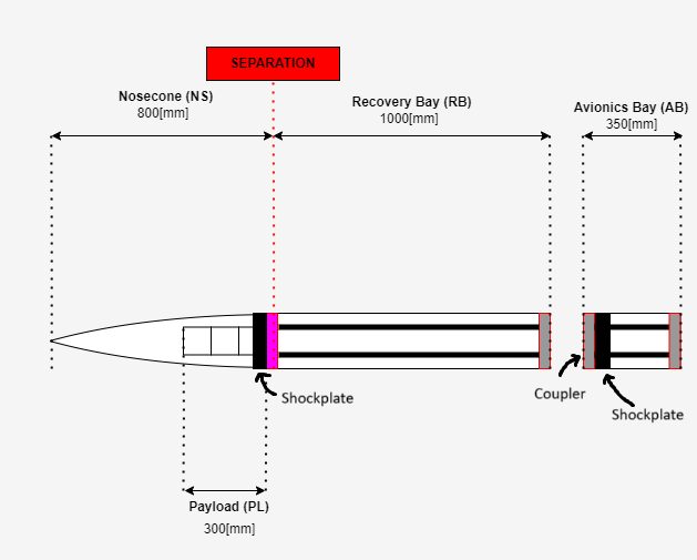
At apogee, the rocket separates into two parts thanks to the Separation Mechanism (SM) to deploy the parachute. Both parts of the rocket, i.e. the Nosecone Bay and the remaining Launch Vehicule are connected to the parachute via the shockplates. The role of the shockplates are to withstand the parachute deployement and to hold the two parts of the rocket.
¶ Definitions and Abbreviations
- SM: Separation Mechanism
- NSB: Nosecone Bay
- AVB: Avionics Bay
- PLB: Payload Bay
- FoS: Factor of Safety
- TCDC: The Countdown Company
¶ Relevant Knowledge Needed
Previous Designs:
You might want to read the documentation of the previous shockplates:
Relevant requirement:
- 2024_C_SE_ST_REQ_10
Parachute opening deceleration
The ST shall withstand a tensile acceleration of [30]g applied on the parachute's attachment points with an additional FoS of [2].
We decided to go for two identical shockplates (i.e. same base, only difference in holes for cables, etc.). The limiting interface was the one between the female coupler at the top of Avionics Bay. Since the back of the rocket weights way more than the NSB, the upper shockplate is oversized.
Shockplates locations:
Advantages and disadvantages of two different shockplates:
Nosecone Bay shockplate is not oversized
Makes designing easier
Need two completely different pieces and technical drawings
More expensive and longer manufacturing
Advantages and disadvantages of two identical shockplates:
Reduces cost and manufacturing time
Requires only small changes between the two designs and technical drawings
Follows the interchangeability philosophy set by structure
Nosecone Bay shockplate is oversized
The advantages of two identical shockplates being very interesting, we decided to accept an oversized NSB shockplate and to go for two identical ones.
¶ Design
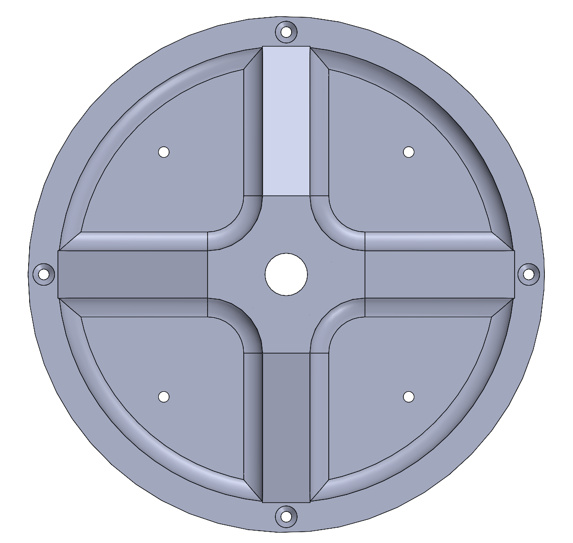
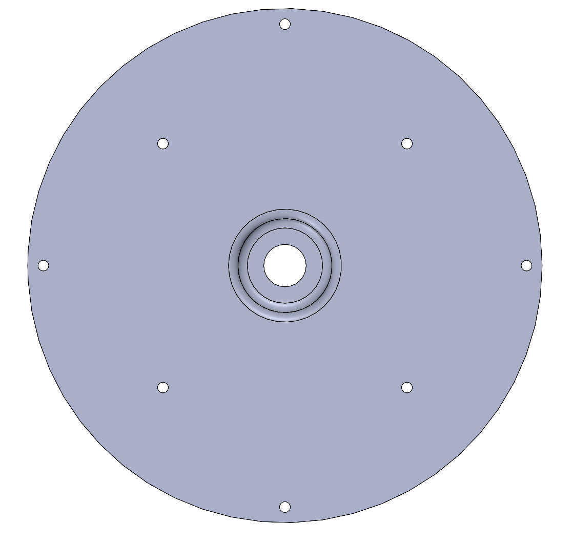
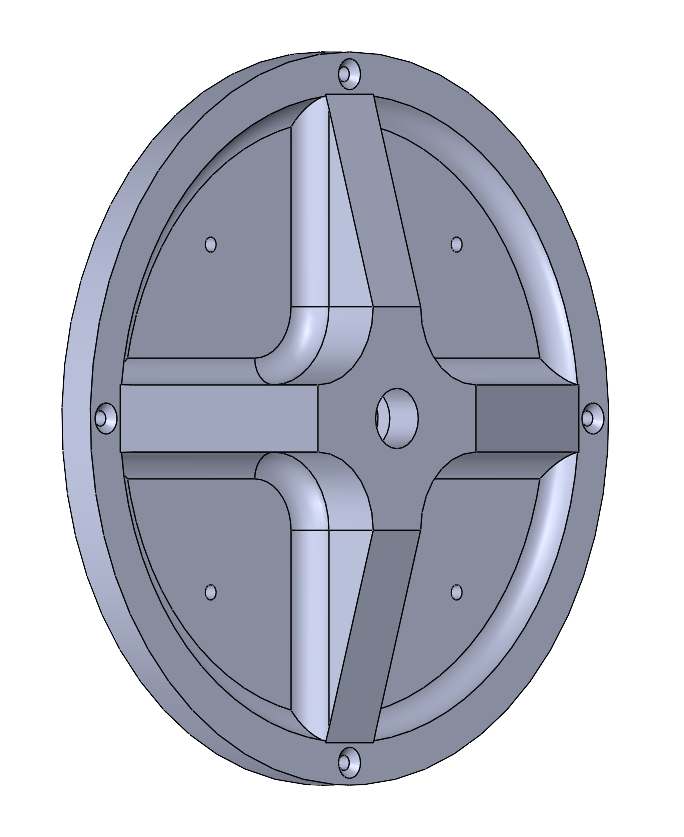
After much turmoil because of the complexity of the coupler and the integration diameter (which changed from 170 mm to 160 mm) we finaly could agree on a design which is compatible with the Payload bay and the coupler. The four inner holes are for the screws that will connect the shockplates to the Avionics Module and the Payload. The four outer ones are for the screws that will link the shockplates to the coupler in Avionics bay and to the Payload Bay. At the center is the hole for the M12 ring screw on which the parachutes ropes will be attached to. Further modifications need to be done to include cables and cameras.
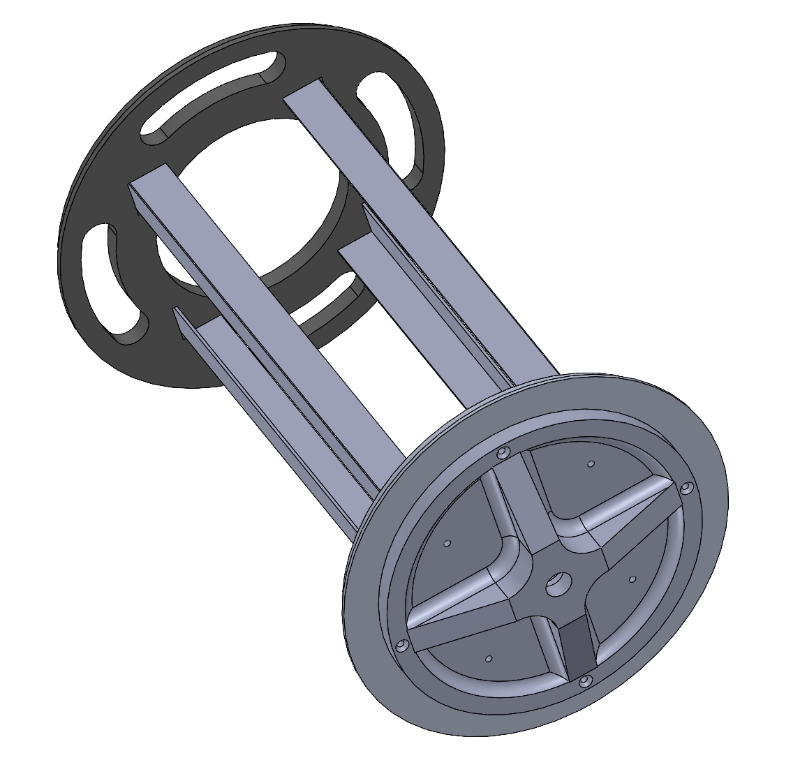
Front, back and 3/4 side view:
Assembly of the PLB together with it's shockplate:
We had the following production options:
- Classical machining in Aluminum:
Conventional, knowledge about what can be done and what cannot
Design freedom limited by machining possibilities
Aluminium heavier and less resistant than carbon option
- 3D printed carbon fibre with The Countdown Company (TCDC):
E/ ratio extremely interesting (advantages of light but resistant carbon fibres)
Broader design options/freedom due to 3D printing
Costs less than conventional machining
New technology in progress
Requires lot of coordination with the TCDC team
Since TCDC's technology is new, we've decided to favour conventional machining for the sake of safety. We will continue to work with them in parallel to develop carbon shockplates, with the ambition of integrating them into Firehorn I and Firehorn II.
¶ Simulation
The material chosen is Al 6082 T6 (isotropic) with following main properties:
- E = 70 GPa
- Poisson's ratio: = 0.33
- Yield strength : = 240 MPa
The shockplate must resist an acceleration of 30g:
N
This load is applied on the inside of the M12 nut hole (A = 310 mm^2) which gives us the following stress:
186 MPa < 240 MPa.
Further simulations will be done to ensure that there is no plastic deformation.