¶ Introduction
¶ Purpose, Objective and Scope
This document provides a detailed Manufacturing Procedure (MAP) for the mold, pre-preg application and assembly of the mini-ABRs (specifically the HABR variant) as part of the ABR PdB. This document also serves as an additional support MAP for all future pre-preg manufacturing.
The primary objective of this document is to provide clear guidance to technicians and team members involved in the manufacturing process. By following this procedure, readers will:
- Understand the necessary materials, tools, and equipment.
- Learn the correct sequence of operations to ensure successful manufacturing.
- Identify potential challenges and best practices to avoid defects.
- Ensure repeatability for future manufacturing runs.
This document covers:
- Material selection and preparation
- Mold preparation and release agent application
- Layup process and fiber orientation
- Curing preparation
- Assembly
¶ Definitions and Abbreviations
- ABR : Anti-Buckling Ring
- HABR : H (shape) ABR as defined in the PDB DJF
- Pre-preg : Pre-impregnated fibers
- Peel ply : Synthetic cloth that you drape over your epoxied surface as the epoxy sets up.
- Bleeder : Polyester fabric that is designed to allow airflow throughout the vacuum bagging process as well as bleed out an excess resin in a composite part.
¶ Applicable and Reference Documents
¶ Parts List
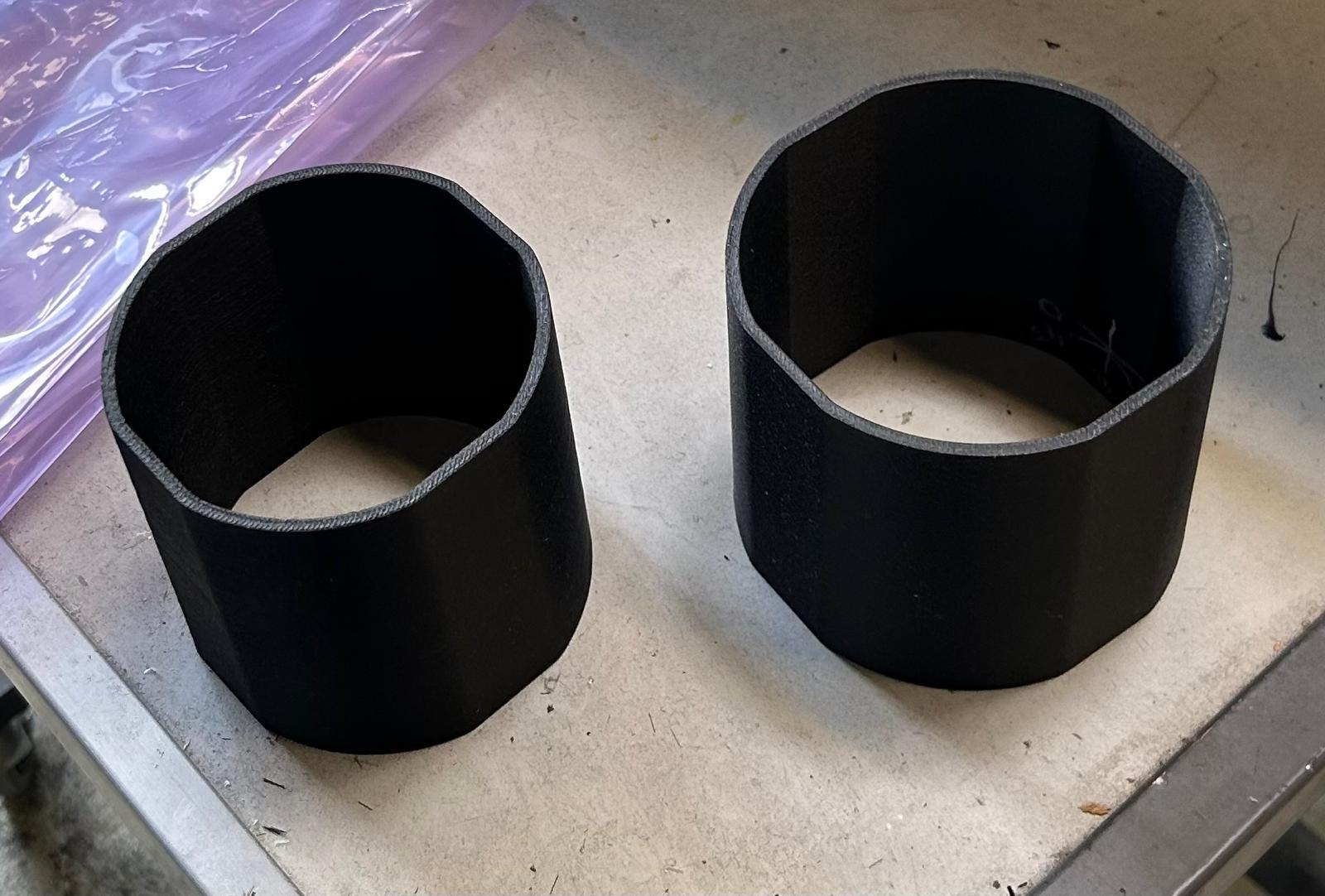
The quantities listed here are for 5 completed HABRs: the rings come in the form of 100mm high tubes from which you will cut 5 individual rings from before the assembly step.
| Description | Part Ref | Qty |
|---|---|---|
| Outer tube | 1 | |
| Inner tube | 1 | |
| Spacer | 5 |
¶ Pre-Operations Checklist
¶ Participants
Number:
¶ Raw Material
| Check | Item | Qty |
|---|---|---|
| PET-CF (Mold and Spacers) | x | |
| Mold Primer | 1 | |
| Mold Release | 1 | |
| Pre-preg | x | |
| Tacky tape | x | |
| Vacuum film | x | |
| Peel Ply | x | |
| Bleeder | x | |
| Perforated film | x | |
| Epoxy | x |
An x means you should prepare enough for your use case, for the mini-ABRs we needed almost two full rolls of APCO pre-preg for example.
Everything should be rated for high-temperatures (>110°C).
¶ Tools
| Check | Item | Qty |
|---|---|---|
| paper towels | x | |
| cutter | x | |
| gloves | x | |
| spray glue | x | |
| vacuum connector | 2 | |
| protection glasses | x | |
| sanding paper | x | |
| carbon rated saw | 1 | |
| hack saw | 1 | |
| hammer | x | |
| wood chisel | x | |
| scissors | x | |
| ruler and square | x | |
| vacuum pump | x | |
| carbon oven | x | |
| barometer | x | |
| clamp | x | |
| spiked rolling pin | x |
¶ Technical drawings
Possible improvements:
- Male mould for the exterior ring and female mould for the interior ring
- Mold with internal flanges (flanges should have an angle to help them slide against each other when hitting them)
- Try to make the mold a color other than black
- Reduce the clearance angle
¶ Mold preparation
Design the molds with a small clearance angle (<1°), this should help with removing the mold but be aware that a bigger clearance angle will make the applications of the pre-preg awkward.
After printing the molds out of PET-CF, cure them at 110°C for 9.5 hours before applying the mold primer and release.
As per the datasheets:
¶ Mould primer
To seal micro-porosities
- Wipe-On mould primer:
Use a clean lint free cloth or paper towel, wipe on in a straight line overlapping between applied edges.- Leave On mould primer for [min]:
The surface should be completely dry and tack free
before applying additional coats.- Repeat steps 1&2 five times.
- [h] curing at T_
Ensure to change cloth each coat.
A total of 6 coating layers are necessary
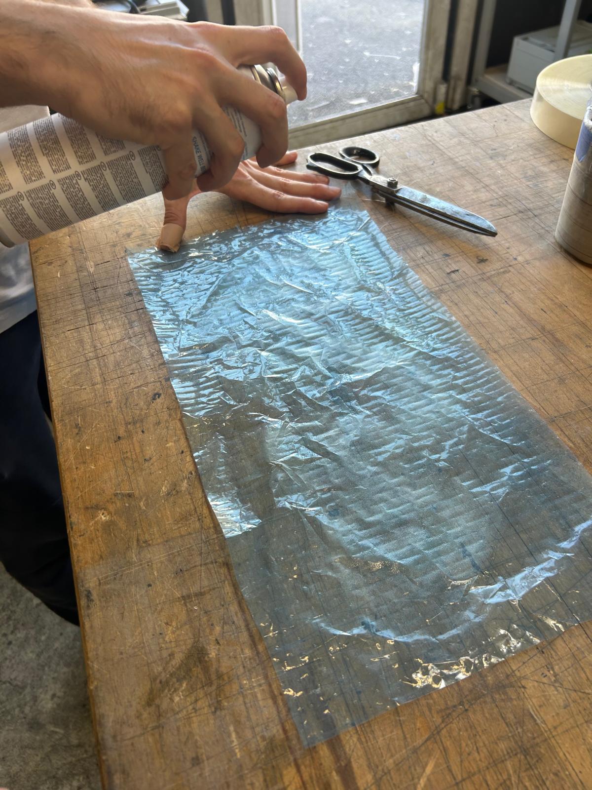
¶ Mould release
To make give high slip, high gloss surface finish
- Wipe-On mould release:
Wet the paper towel with XTEND ACR-HS until it is wet but not dripping. Gently squeeze the towel into a ball to soak the AXEL XTEND ACR-HS throughout the towel. Wipe on to the mold surface using smooth even strokes. Apply a thin, uniform coating and allow the release agent to evaporate.- Wipe-Off mould release:
Using a clean cloth lightly wipe over the surface removing any excess release agent- [min] waiting.
- Repeat steps 1-3 four times.
- [min] curing at T_
A total of 5 coating layers are necessary
¶ Cutting the Pre-preg
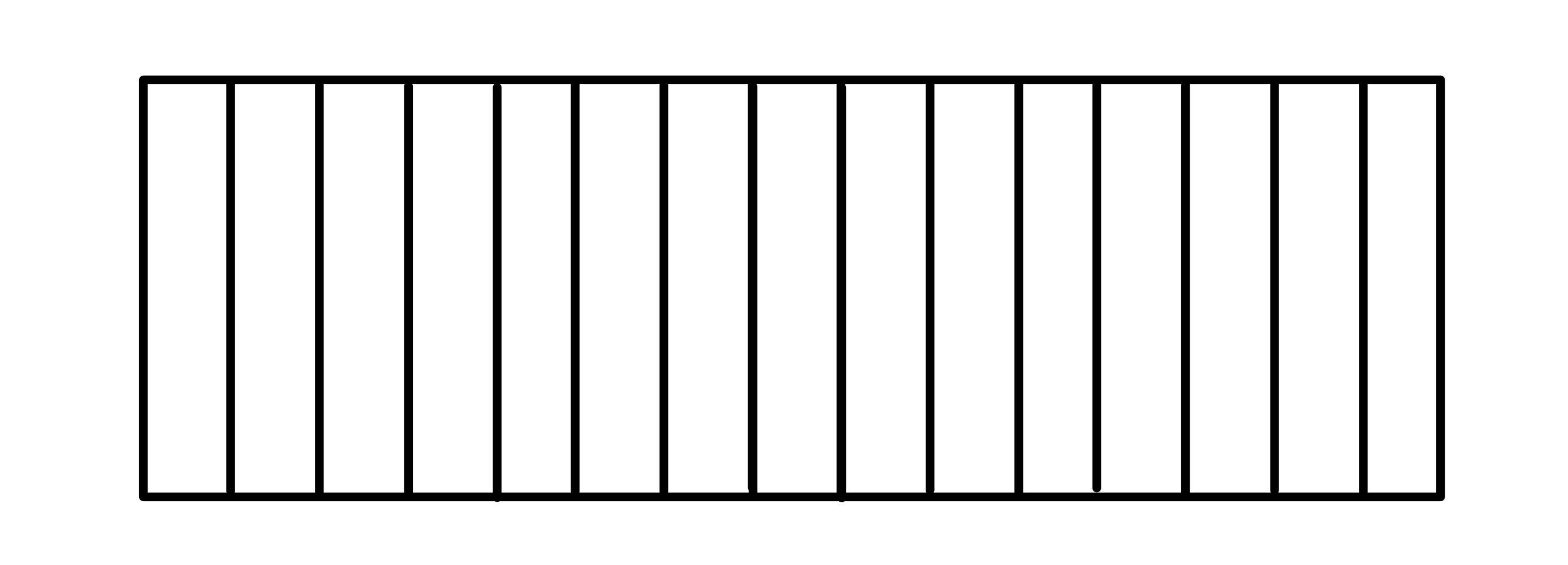
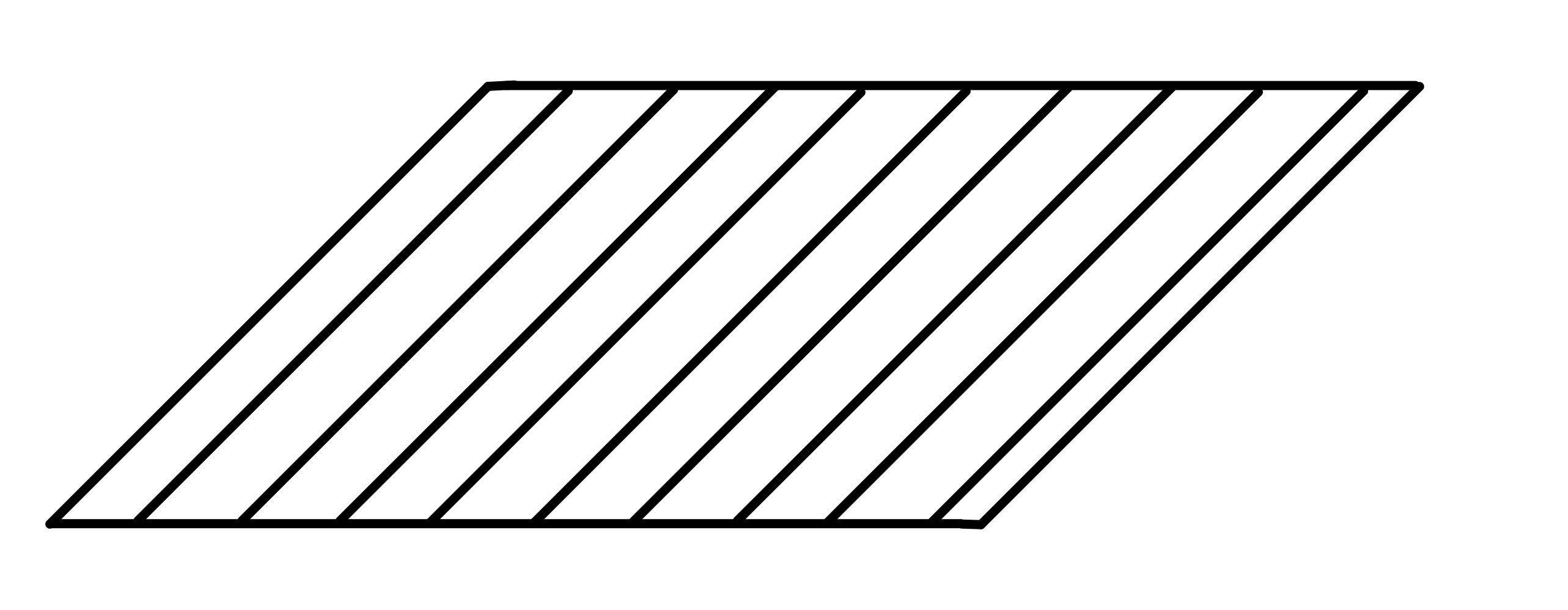
The goal is to cut strips of pre-preg with the correct fiber orientation to match the predetermined layup : [0, 45, 0, -45, 90, -45, 0, 45, 0].
We decided that 0° represented fiber going along the perimeter of the tubular mold and 90° represented fibers going along the axis of the tubular mold.
0°
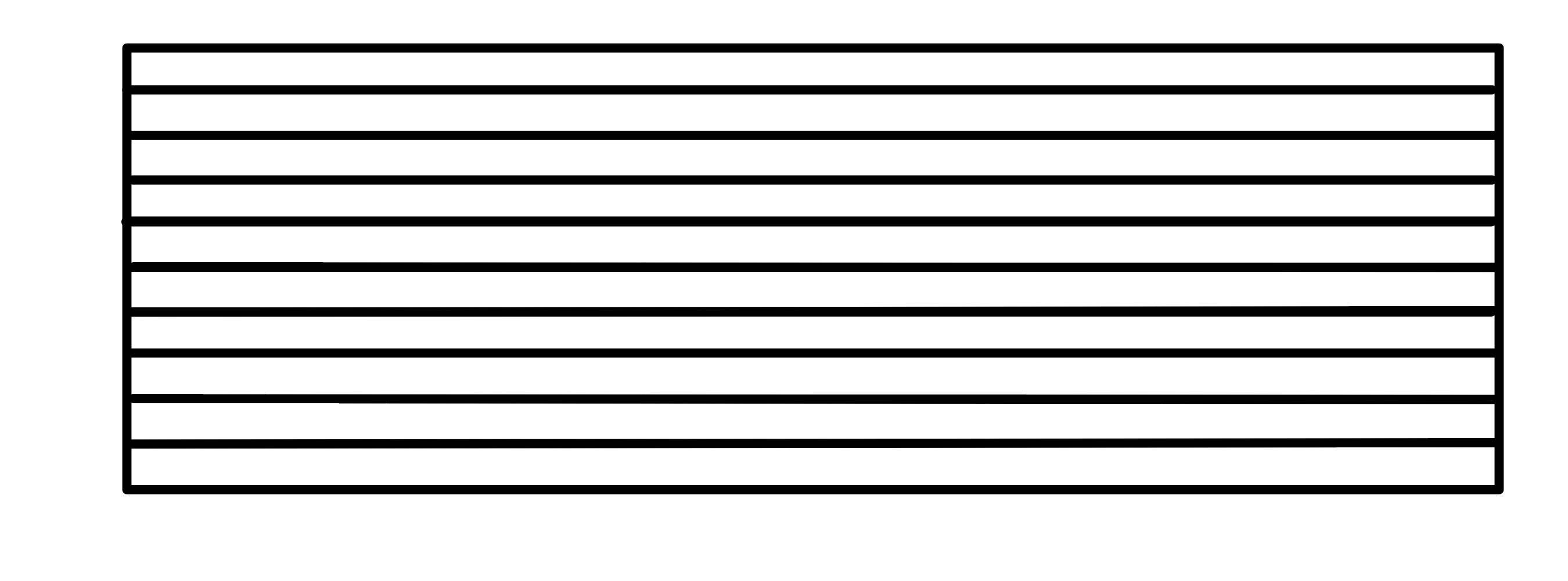
90°
45°
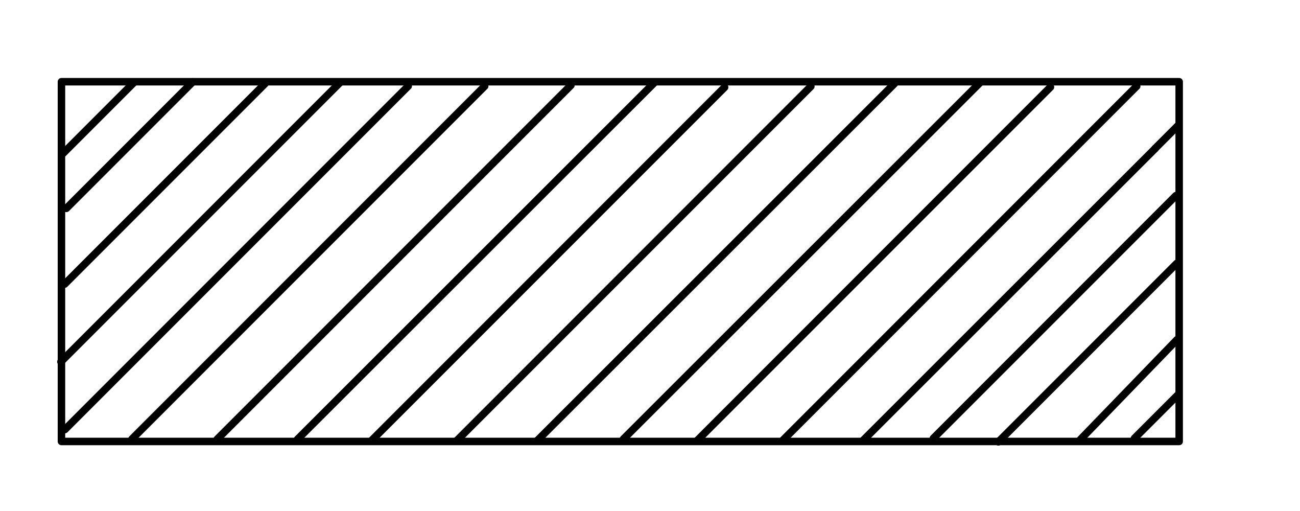
Each strip is rectangular with a height matching that of the mold with an added 0.2-0.5mm in case the strip is placed crooked. The length of each strip should be the a bit bigger than the circumference of the tubular mold but keeping in mind that the 0° fiber need to overlap by about 10mm per 100g (grammage of the pre-preg). The ±45° fibers also need to overlap while the 90° fiber don't need one.
The idea is to connect the fibers all along the direction in which the stress they need to counter will be applied.
(The ±45° strips can also be cut as parallelograms to align the fibers more easily)
To avoid confusion, write on each strip the layer number and direction of the fiber.
Finally, use the spiked rolling pin to add small perforations in each strip. Roll over each strip twice.
¶ Applying the pre-preg
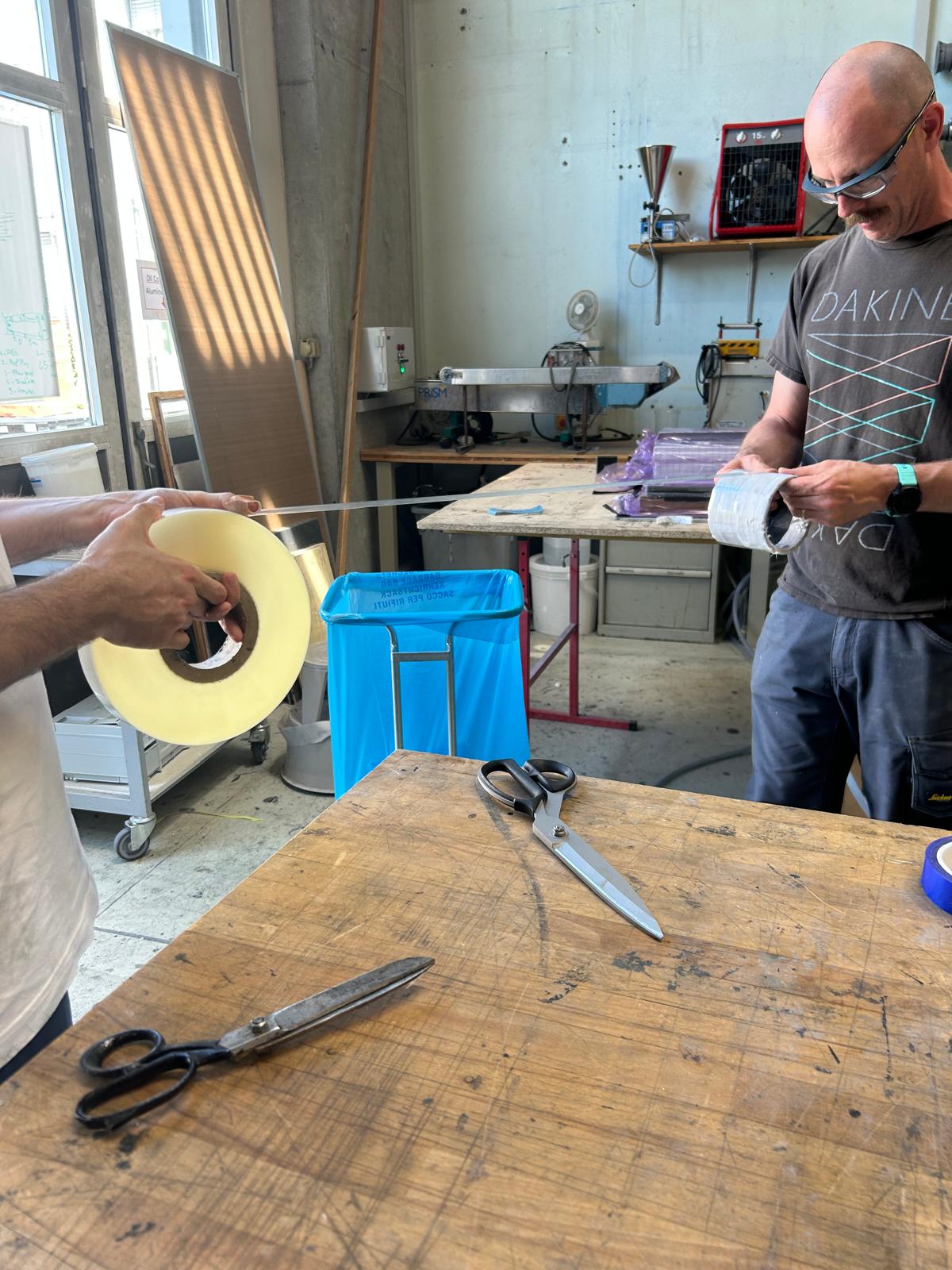
At least two people needed for this step
Draw a reminder of the fiber orientation on the mold
The first strip is the hardest to apply because of the non-sticky surface of the mold.
Operators must intermediate vacuum after the first layer and after each subsequent three layers.
Try to offset the area where each 0° layer overlaps to distribute the thickness around the part.
- Draw a straight line on the mold (or previous layer) along the axis of rotation to align the strip.
- Align the strip with that line.
- One operator applies the strip and rotates the mold while another keeps the strip under tension and verifies the alignement (in case of a third operator, he can apply the strip instead).
- Go slowly and massage along the fiber to remove folds and help the strip take its final shape.
- If at the correct layer (as defined above): vaccum to help compact the previous layers.
- Repeat until final layer.
In the case of a gap:
- Cut a strip by following the 10mm/100g rule.
- Apply the strip to the gap by aligning the fibers
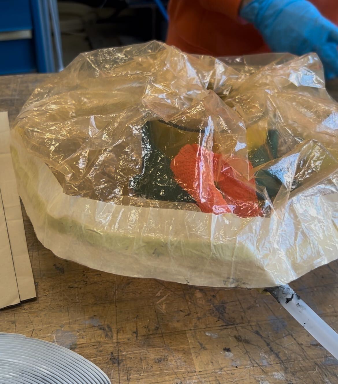
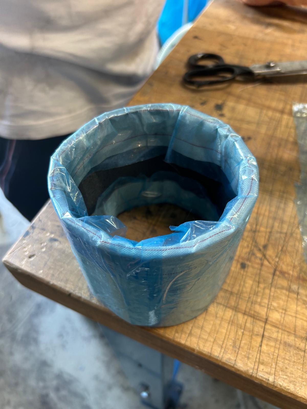
¶ Intermediate vacuum
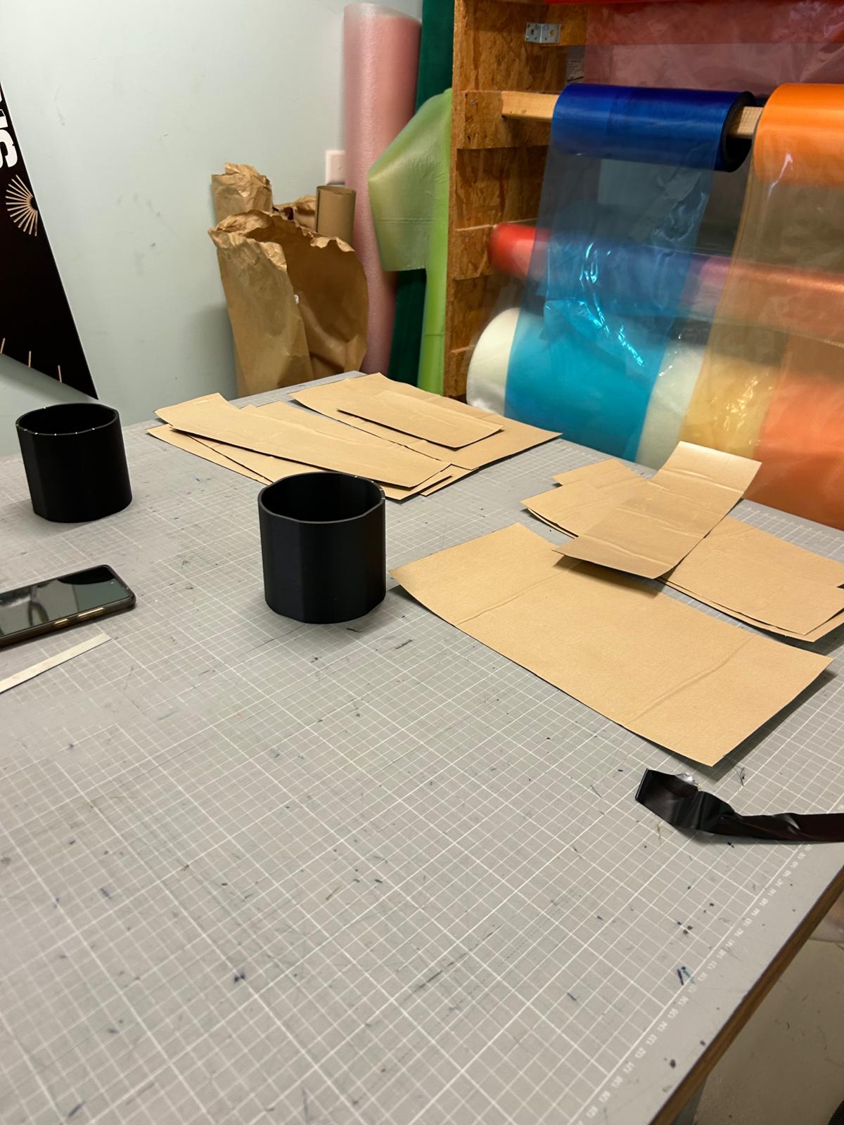
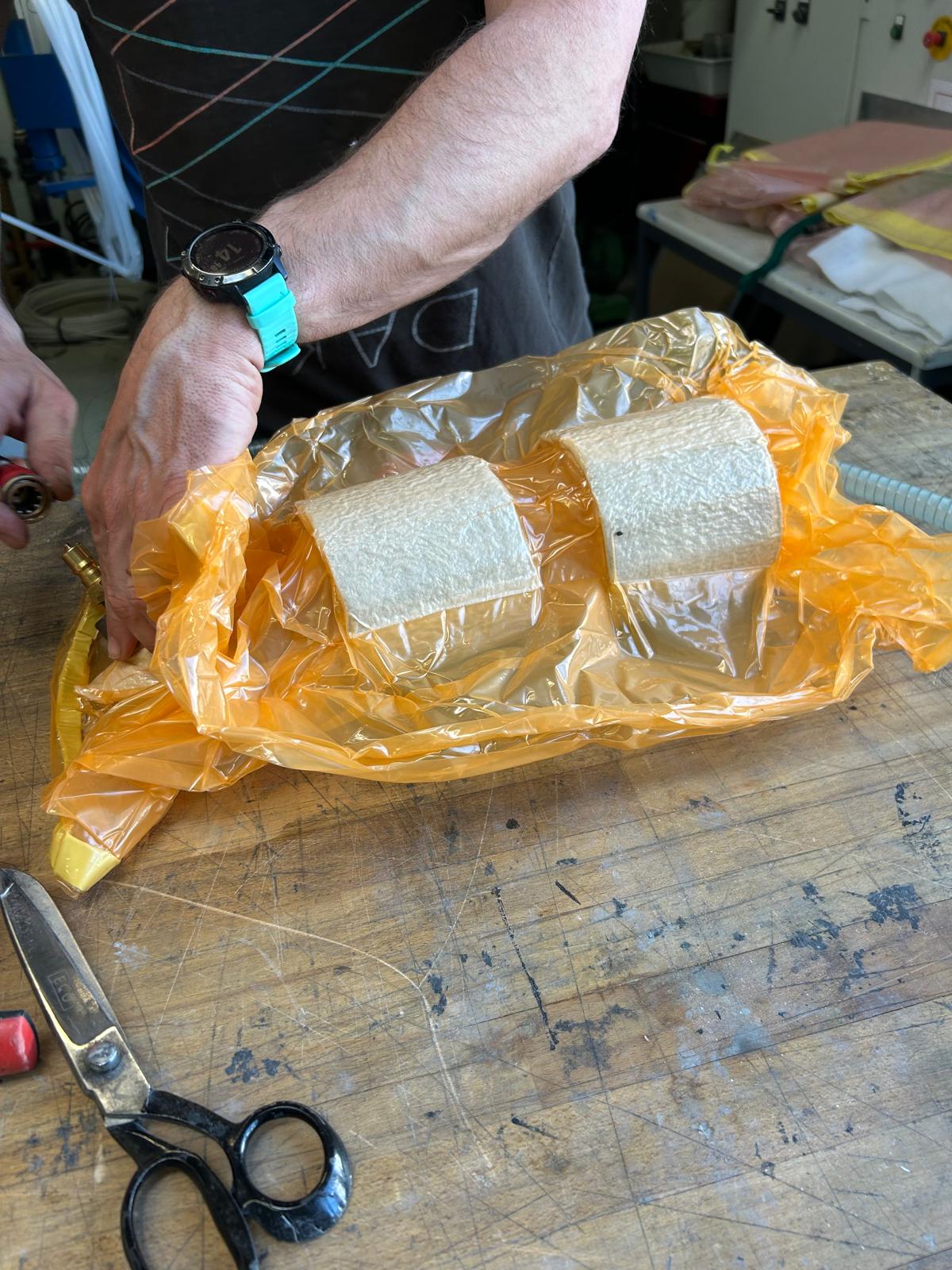
You can make a re-usable vacuum bag.
- Make a tubular bag out of vacuum film and tacky tape.
- Pass the vacuum bag through the tubular mold
- Fold the bag in on itself to seal it
- The mold should be entirely contained inside the bag and a vacuum hose should be inserted hermetically inside the later
- Vacuum the piece for 10-15 mins
¶ Preparing the mold for curing
¶ Peel ply
Tightly apply the peel ply around the last layer. Use spray glue to attach the peel ply to the interior of the mold (you might need to cut the peel ply into squarish strips inside the mold so that it follows the tubular shape). Secure it using shrink tape (transparent tape on image) but add some high-temperature tape at each extremity of the shrink tape (blue tape).
¶ Perforated film
Next wrap some high-temperature perforated film around the previously applied tape after spraying it with glue.
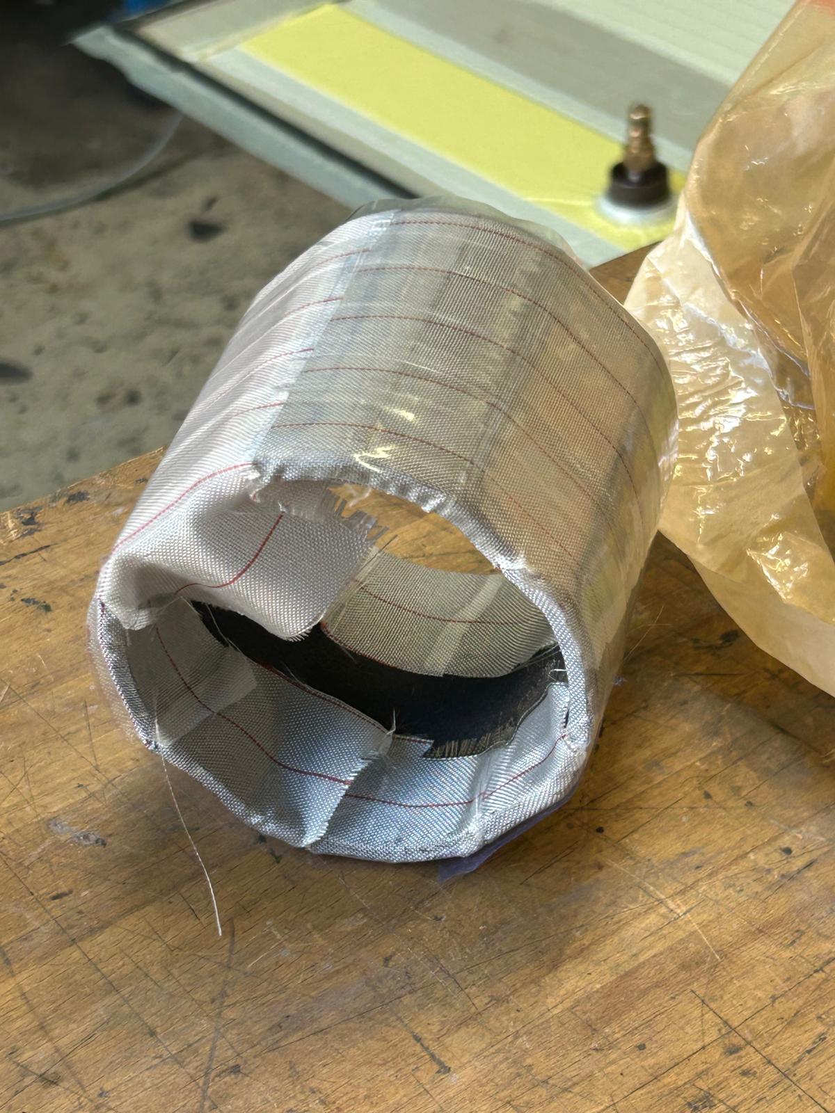
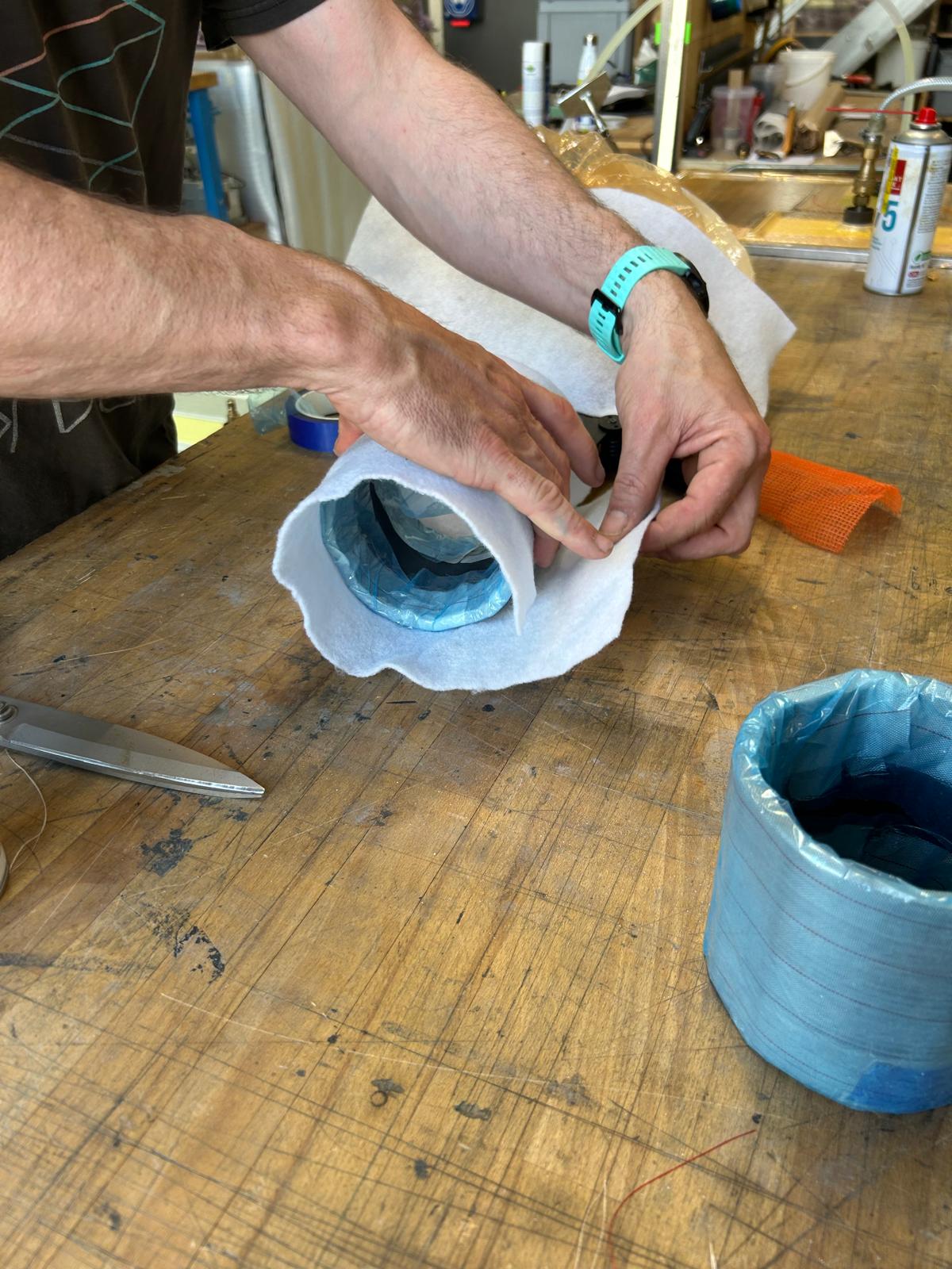
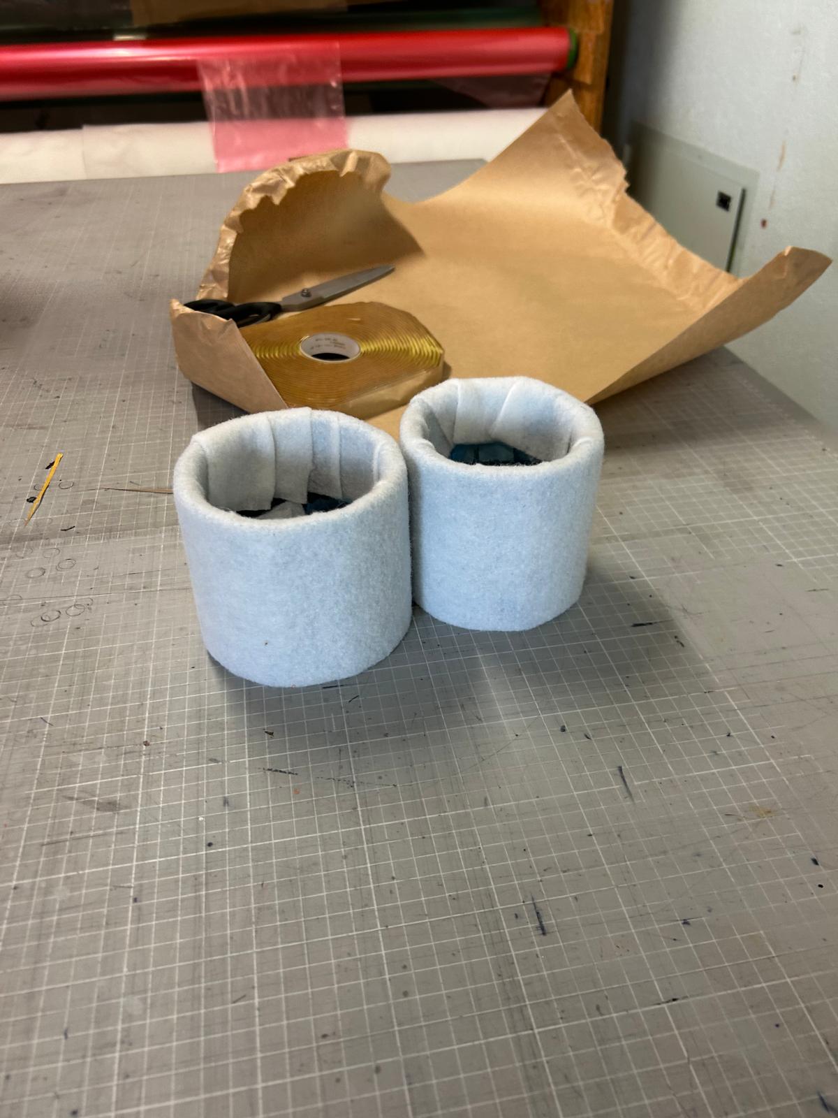
¶ Bleeder
Finally, wrap some bleeder frabic around the perforated film using the same technique as for the peel ply. You can use glue to stick the two ends of bleeder fabric together.
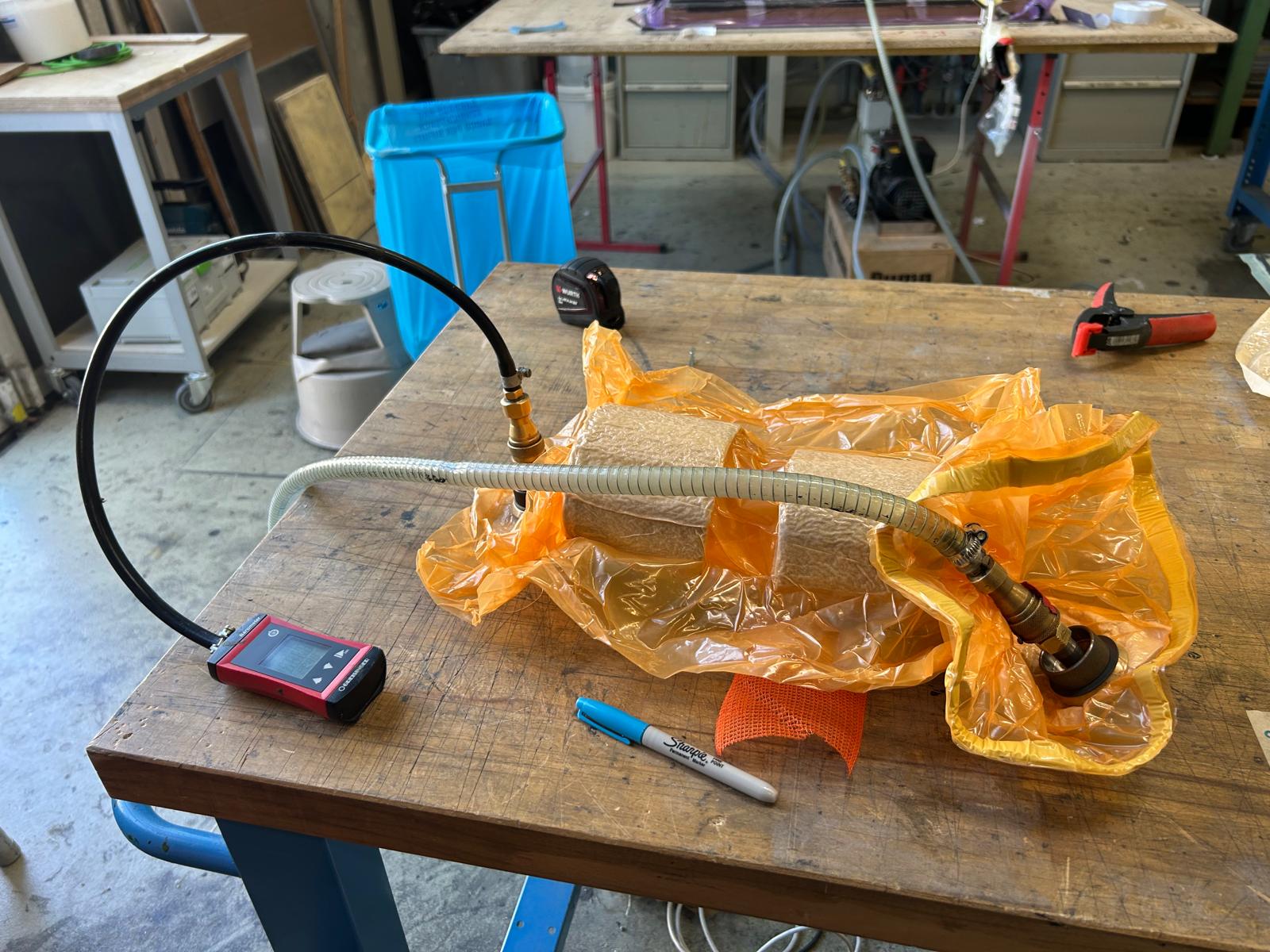
¶ Vacuum bag
Make a new vacuum bag following the same steps as for the first one but this time add two vacumm connectors to it. One will be used to suck the air out of the bag while the other wil serve as a connector for the barometer.
Perform a drop test to verify the integrity of the seal: each minute, write down the current reading from the barometer for a total of 10 minutes.
¶ Curing cycle
- Go up to 63°C in 10 mins
- Stay at 63°C for 30 mins
- Go to 110°C in 20 mins
- Go to 103°C in 10 mins
- Stay at 103°C for 2.5 hours
- Go to 35°C in 2 hours
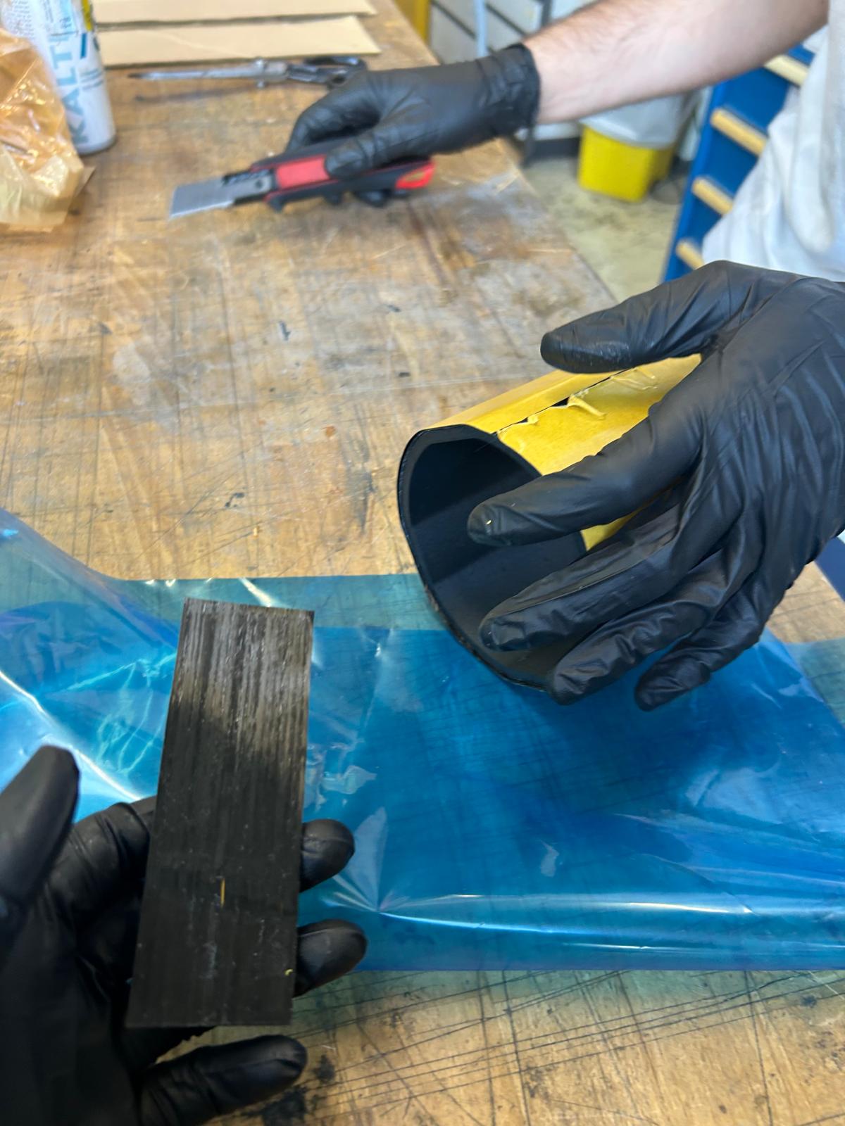
¶ Demolding
If all went well, demolding should be easy enough. Simply use the wood chisel and hammer to slightly separate the mold from the part and slide the part out.
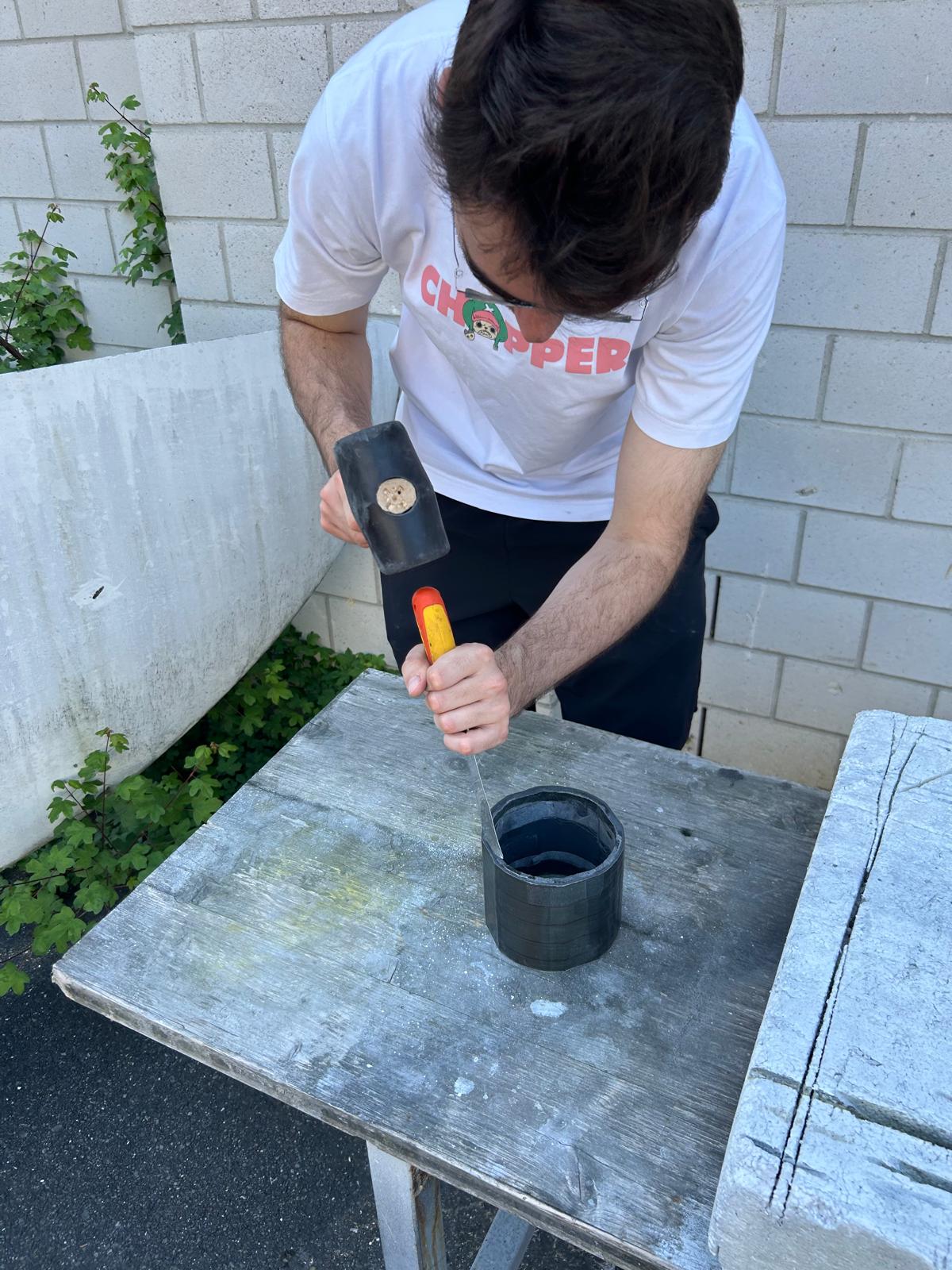
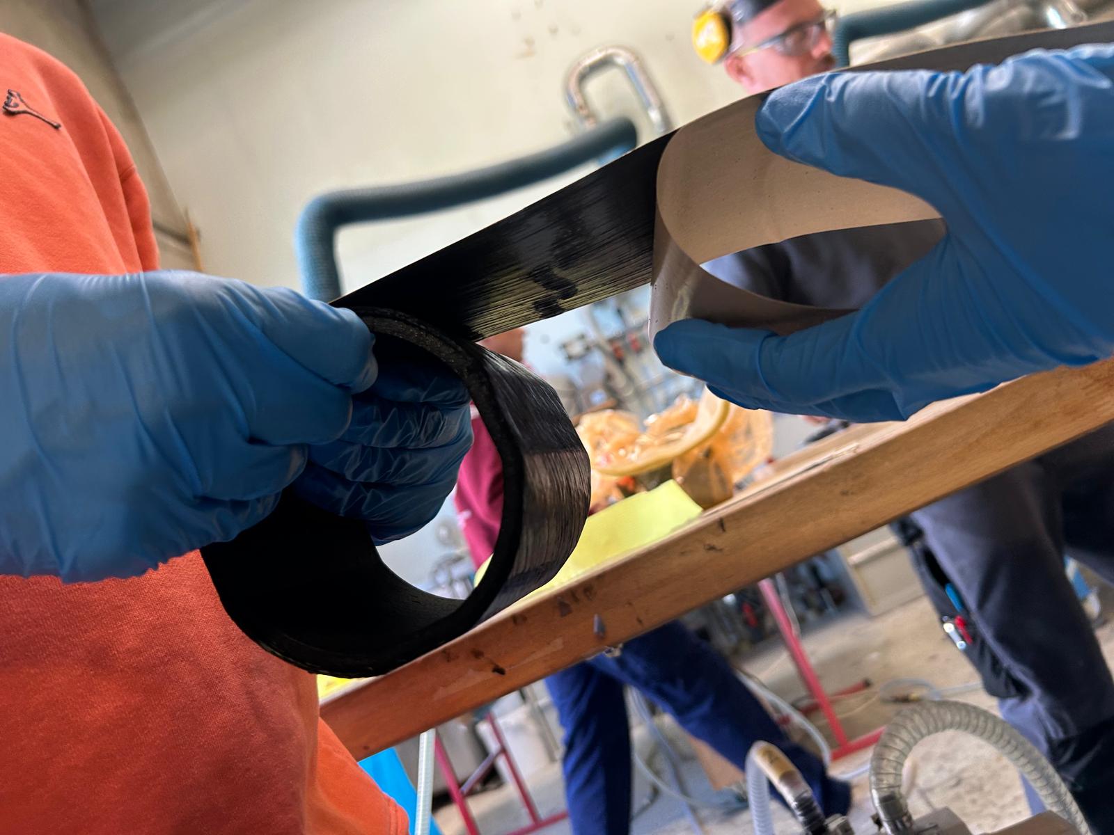
If like us, the part sticks to the mold:
- Invert he blade of the hacksaw and insert in inside the mold to cut it from within
- Cut a groove up along the whole tube up to the carbon part while being careful not to tear the first layer
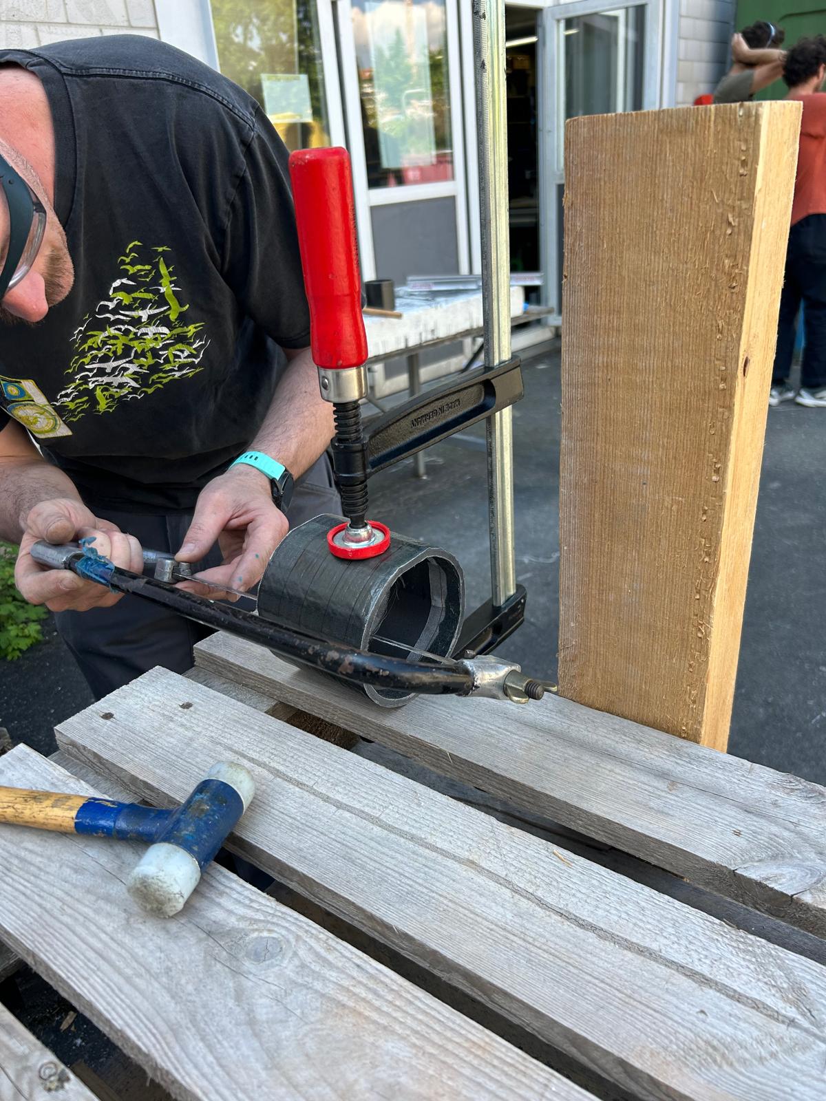
- Clamp the tube on its side to a table while a second operator holds the tube to keep it from rotating
- Peel the mold off the part with the wood chipper and hammer by hitting near the groove
¶ Assembly
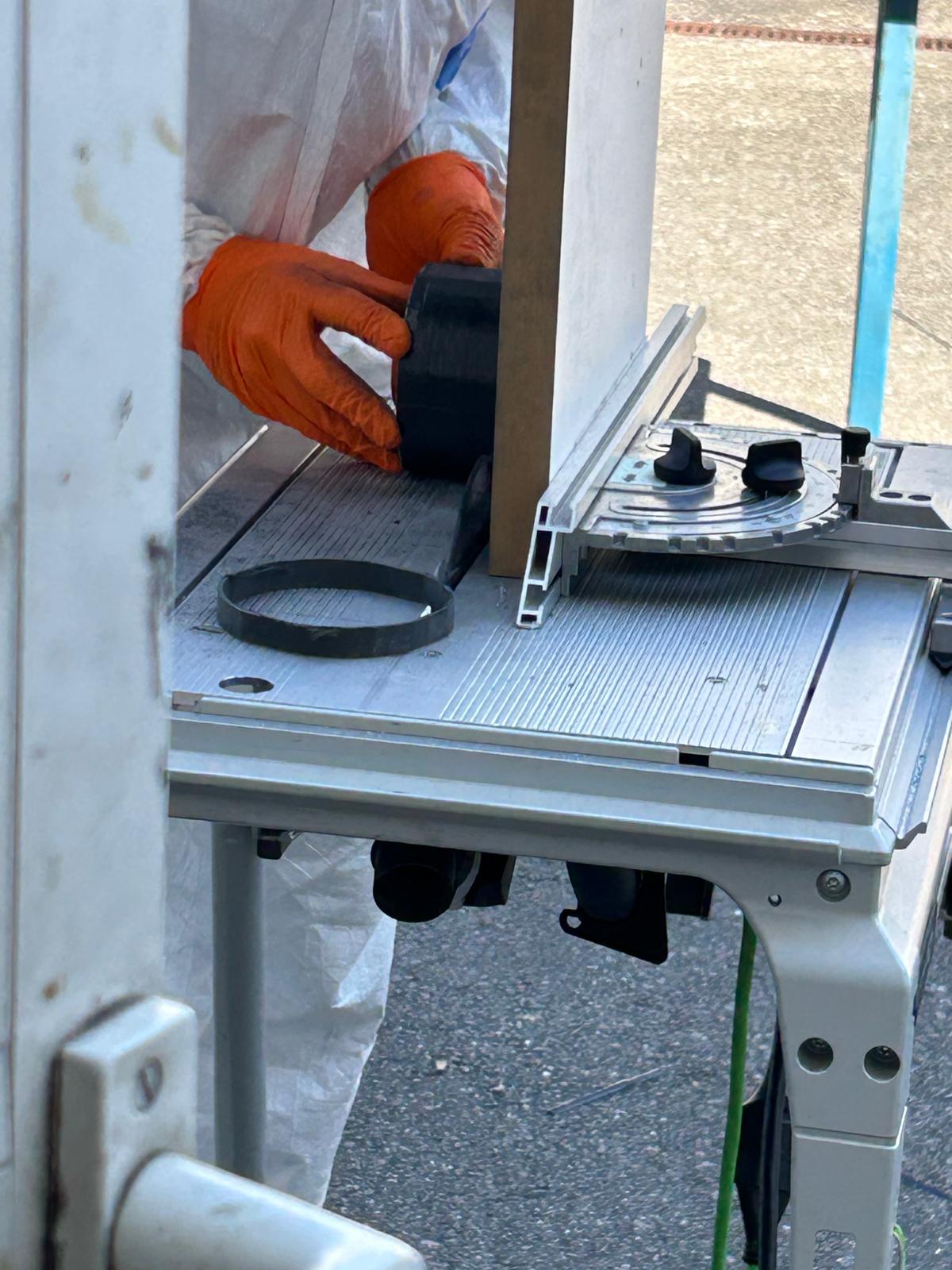
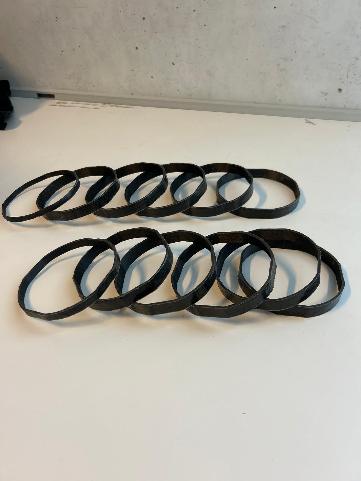
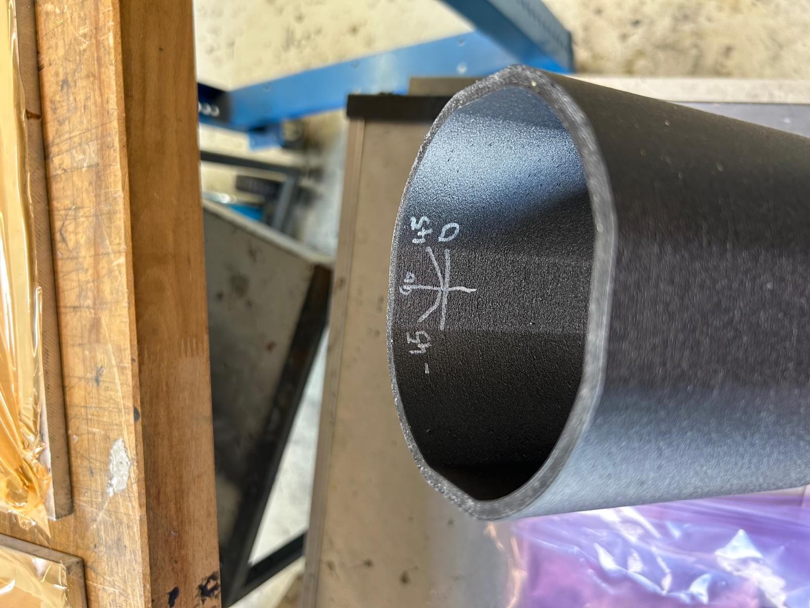
- Cut the tubes into 15mm (18mm) rings
- Measure the true dimensions of your carbon rings and print the PET-CF spacers accordingly
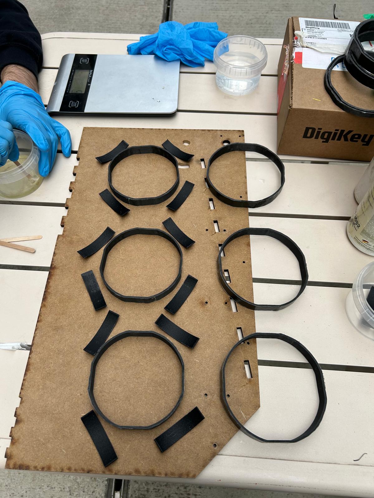
- Sand the rings and spacers using 80grit sandpaper
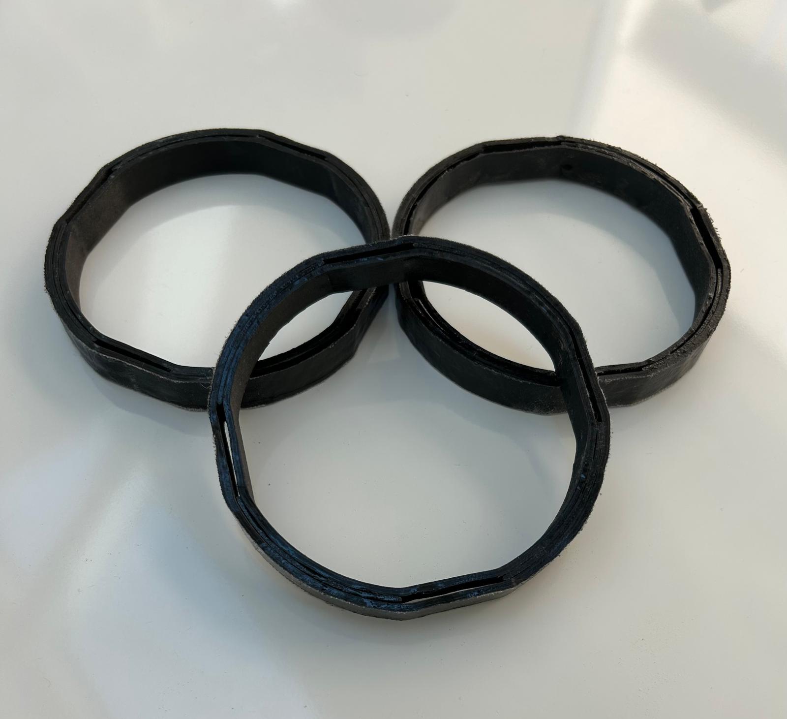
- Stick the inner ring, spacer and outer ring together using epoxy (use appropriate protection !!)
4.a. Mix 70% epoxy and 30% hardener for 5 mins before applying
4.b. Apply good amount to the rings and both sides of the spacers before curing for 24h