¶ Introduction
This document presents the design and the engineering process behind the conception of the cryogenic tanks for the Firehorn rocket.
This year two propellants are used : liquid oxygen at a temperature of -183°C and ethanol. Two tanks are used to store each liquid. They are connected together by the midbay, a structural element where different parts of the plumbing are stored. The link between the tanks module and the others modules of the rocket is achieved with couplers.
¶ Abbreviations
- LOx : Liquid Oxygen
- ETH : Ethanol
- FoS : Factor of security
- TIG : Tungsten inert gas
- FSW : Friction stir welding
- EBW : Electron beam welding
¶ Applicable and Reference Documents
- Design Requirement List (DRL)
- Design Justification File (DJF)
- Low-Level Interface Management (LLIM)
- Test Specfication & Procedure (TSP&PR)
- Test Report (TPRT)
- Simulation report (SR)
- Technical Drawing (TD)
- Software Design Document (SDD)
- Manufacture Procedure (MP)
- Assembly Procedure (AP)
- Operation Procedure (OP)
¶ Main requirements and loads
-
2024_C_SE_ST_REQ_02 Tank Structural Role
The tanks shall withstand all the flight loads and constrains. -
2024_C_SE_ST_REQ_03 Tank Volume
The tank shall have an internal volume of [25][+/-0.25]L. -
2024_C_SE_ST_REQ_04 Tank Length
The tank bay shall have a maximum length of [650]mm. -
2024_C_SE_ST_REQ_07 Tank Mass
The total mass of the tank module shall be maximum [10100]g. -
2024_C_SE_ST_REQ_08 LOx Isolation Time
The tank shall be able to keep at least [20]L of liquid oxygen at a temperature of [-183]°C and a pressure of [60]bar in a liquid state for [8]min. -
2024_C_SE_ST_REQ_09Tank Nominal Pressure
The tank shall be designed to sustain a maximum operation pressure of [60]bars. -
2024_C_SE_ST_REQ_10Tank Burst pressure
All SRAD and modified COTS pressure vessels constructed entirely from isotropic materials (e.g., metals) shall be designed to a burst pressure no less than 2 times the maximum expected operating pressure, where the maximum operating pressure is the maximum pressure expected during pre-launch, flight, and recovery operations. -
2024_C_SE_ST_REQ_12Tanks Interchangeability
The tank containing the liquid oxygen shall be mechanically identical to the tank containing the liquid ethanol so that both tanks may be interchangeable. -
2024_C_SE_ST_REQ_25Tanks Scalability
The tank design shall be upgradeable to contain [60]L for the [30]km flight by only changing the length of the tank. -
2024_C_SE_ST_REQ_31Compression Forces Resistance
The structural load-bearing elements shall withstand axial compression loads of [10000]N with a FoS of [1.5]. -
2024_C_SE_ST_REQ_32Added Compression Mass
The axial compression load case shall consider the mass on top of the considered module being accelerated at a rate of [6]g. -
2024_C_SE_ST_REQ_33Axial Deceleration Stress
The structural load-bearing elements shall withstand axial tension caused by a deceleration of [30]g on a dry mass of [220]kg with a FoS of [2].
- The tank module must withstand the 60[bar] nominal internal pressure during the flight.
- The tank module must withstand 90[bar] for 90[min] and must be design to resist a theoretical internal pressure of 120[bar].
- The tank, being structural, must withstand all compressives loads, with the rocket engine's thrust and the forces associated to the accelerated mass above the tanks. This sums up to a total compressive load of 21 000 [N].
- When the tank isn't pressurized (i.e. at the end of the engine burn time), it shall resists a tensive stress of 130 000 [N].
¶ Functional Description
The tanks are the parts of the rocket that contain the rocket engine's fuel and oxidizer. This year the rocket is equiped with a bi-liquid engine, and therefore two tank modules are required. One tank is filled with LOx at -183[°C], while the other is filled with ETH. The two propellants are pressurised at 60[bar] using nitrogen gas. Furthermore, the tanks are structrual parts of the rocket which mean they shall withstand all the flight loads and constraints and must be re-usable.
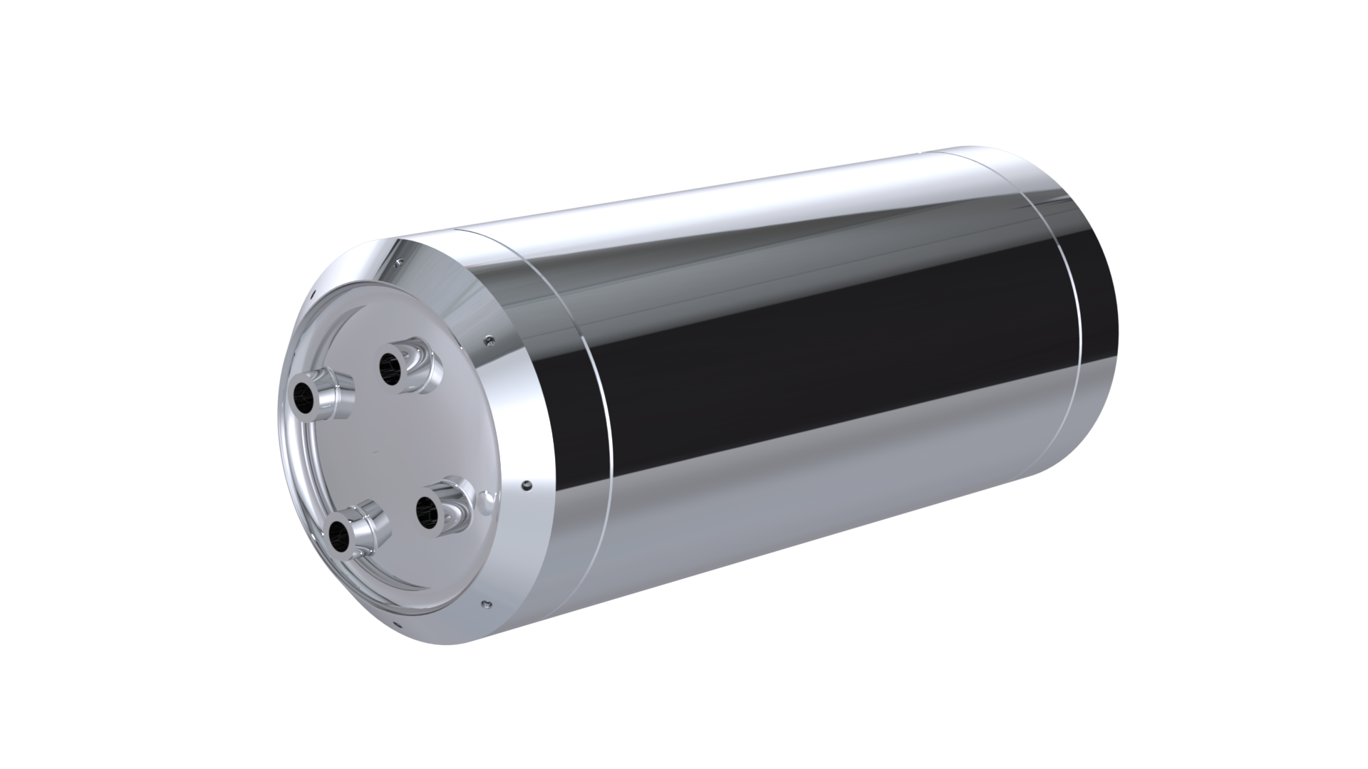
During the take off and the flight, the pressured nitrogen gas is used to push the LOx and the ETH towards the engine via the plumbing system. Four entries are available at each caps ends for the plumbing to connect.
Moreover, the tank has to be able to integrate the new capacitance fill level sensor, a pressure sensor and a pressure relief in case of a rapid increase in the internal pressure. That's why we chose to design the caps with 4 1/2'' holes. Those caps are fitted both on the upper side and on the down side of the tank in order for the tank module to be rapidly interchangeable, and to reduce manufacturing costs and length.
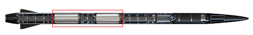
¶ Physical Architecture
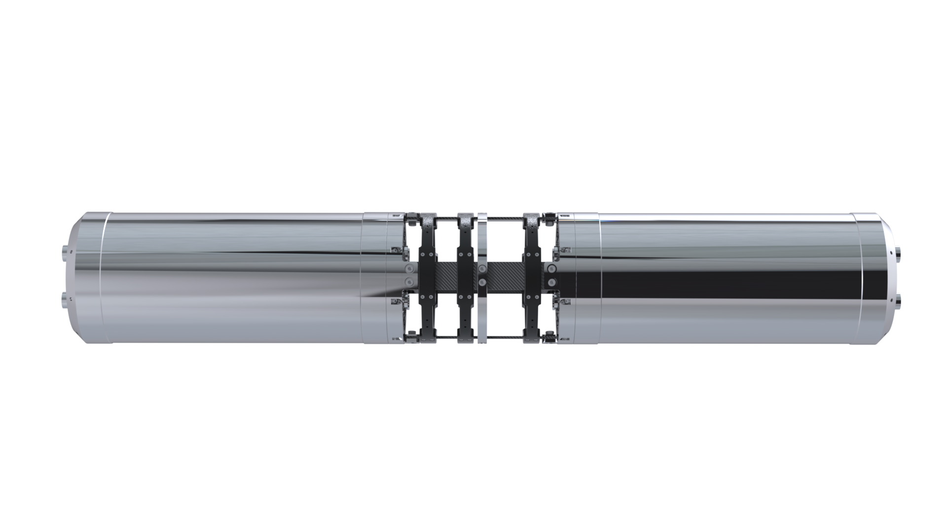
The design shown above is the complete module of the tanks coupled together. The couplers are screwed to the tank's caps to be connected via the rods. The plumbing system is placed in the middle space.
From top to bottom the order of the fuel is : nitrogen gas, ETH and LOx. Some pipes will be placed on the tank's surface as they cannot go through it. Nitrogen pipe for both propellant and ETH exit pipe outside the LOx. These pipes will cover by the plumbing cover.
¶ Parts Tree
¶ COTS Parts Table
| Part Name | Number of Parts | Main Characteristics | Link to Material Data Sheet |
|---|---|---|---|
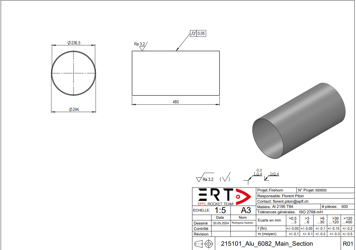
| 215101_Cylindrical_Section | x1 | Main structural element of the tanks, designed to be welded | Al 2195 Datasheet |
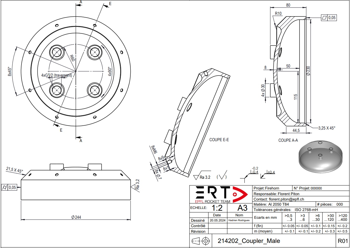
| 214202_Coupler_Male | x2 | Designed to close the tank and link the tank to the rest of the rocket' structure | Al 2050 Datasheet |
¶ SRAD Parts Description
The tank is made of only three parts : The cylindrical main body and the two end caps
¶ 215101_Cylindrical_Section
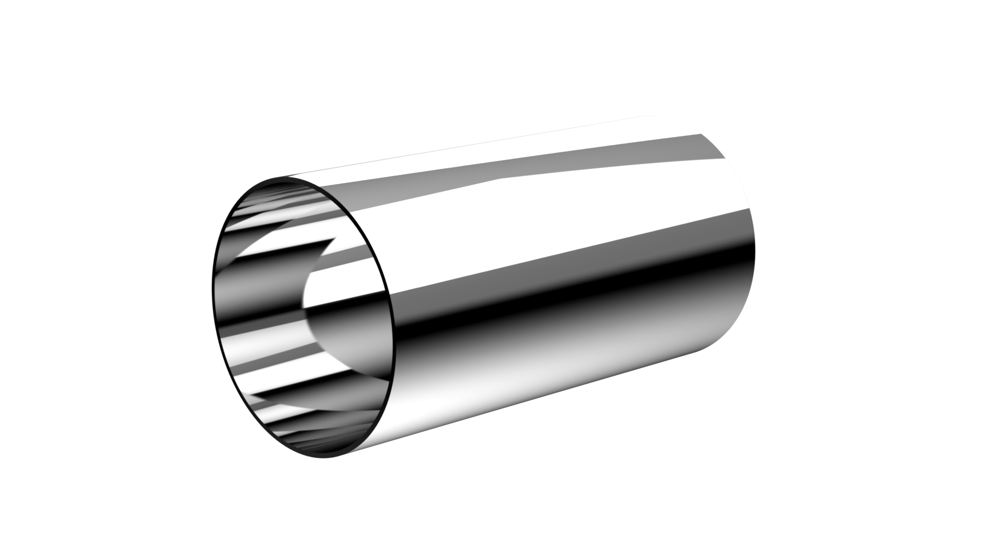
¶ Description
The cylindrical part is rolled out of an Al 2195 T84 plate and will be welded along the longitudinal axis with TIG method. The caps will be welded on the circular perimeter using the same method. The final dimension are 500[mm] for the height and 236.5[mm] for the inner diameter and 243[mm] for the outer diameter. The mass is 3.668[kg]
| Part Name | Number of Parts | Main Characteristics | Link to .SLDPRT file |
|---|---|---|---|
| 215101_Cylindrical_Section | 1 | Lenght : 480[mm] Dia out : 244[mm] Dia In : 236.5[mm] Mass : 3.668 [kg] | 115201_End_Ring.SLDPRT |
¶ Technical Drawings
¶ 214202_Coupler_Male
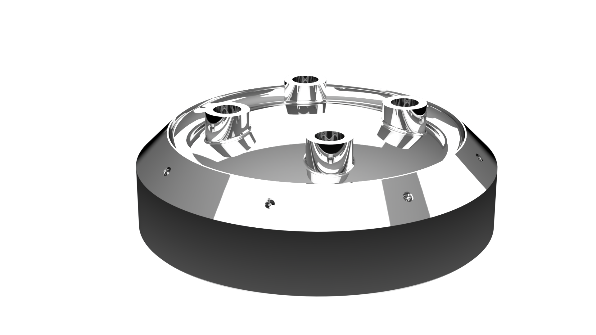
¶ Description
The caps are machined from Al 2050 T84 blocks and are all male-type. The dimensions are 70[mm] for the length and 243[mm] for the outer diameter. The mass is 2.1[kg] each. They are welded on both ends of the cylindrical part with TIG method.
| Part Name | Number of Parts | Main Characteristics | Link to .SLDPRT file |
|---|---|---|---|
| 214202_Coupler_Male | 2 | Length : 70 [mm] Dia out : 244 [mm] Mass : 2.1 [kg] | 115201_End_Ring.SLDPRT |
¶ Technical Drawings
¶ Technical Budget, Margins and Deviation
| Type of value | Units | Requirement Value | Actual Value | Deviation |
|---|---|---|---|---|
| Total Internal Volume | L | 25 | 25.16 | + 0.064 % |
| Total Weight | kg | 10.1 | 7.82 | - 22.57 % |
| Total Length | m | 0.6 | 0.6 | - 0 % |
¶ Design Constraints
¶ Constraints for Production
The main constraint is the welding. The 2195 T84 alloy was chosen for its high yield and tensile strenght performance, a good welding method is needed not to loose the material properties around the welds. FSW and EBW are not possible to operate for our dimensions and budget, therefore TIG will be used as the properties loss is acceptable and as the performances are still excellent.
The tanks being structural parts, their wall thickness was set to 3.5[mm] in order to resist the load cases such as buckling, traction, compression. The caps thickness at the weld spot was also increased in order to compensate the properties loss in this area.
The cylindrical body will be rolled out of a 6.73[mm] plate, this operation will not be simple in order to have a precise cylinder. Then the full tank with the caps will see its thickness reduced from 6.73[mm] to 3.5[mm] on a lathe machine which can be complex if we want to keep the cylindrical shape precise and not harm the alignment.
¶ Constraints for Operation
Sloshing can occur during the flight and can destabilize the rocket. The sloshing being a difficult part of fluids dynamics, only some designs were thought.
-A horizontal grid at the exhaust to prevent the formation of vortex which need to be weld inside the caps before the main welding.
-Rings baffle inside the cylindrical body can be used as anti-slosh structures, these rings would be welded inside the cylinder before the main assembly and their exact shapes is still uncertain.
We need to take account that extra welds on the tank could affect its properties and shape.
The two first produced tank will not be equiped with anti-sloshing structures and will be tested in order to determine if sloshing is really a critical problem in our case. If so, they will be part of the next set of tanks.