¶ Introduction
¶ Purpose
The purpose of this document is to establish a structured framework for overseeing the development and design phases of a sophisticated aerospace system within the context of a student team. As projects in amateur rocketry evolve to encompass greater complexities, it becomes imperative to transcend traditional methodologies. Therefore, this document endeavors to provide a systematic approach tailored to the unique challenges presented by increasingly intricate aerospace endeavors, ensuring coherence, efficiency, and efficacy throughout the project lifecycle.
¶ Scope
This Systems Engineering Plan (SEP) encompasses the management of the development and design phases of the Hyperion Plasma Class (H-PC) project undertaken by the EPFL Rocket Team. The scope of this document extends to all stages of the system lifecycle, including system architecture, design, verification and validation, and documentation. It encompasses the integration of various subsystems and components necessary for the successful realization of the final articles. Additionally, the SEP outlines the processes and methodologies to be employed by the student team to address the increasing complexities of the association's projects, while also ensuring alignment with the team's objectives, resources, and constraints. It is intended to guide the EPFL Rocket Team members in effectively coordinating their efforts and resources to achieve the project goals within the specified timeframe and budget.
¶ Definitions and Abbreviations
- H-PC : Hyperion Plasma Class
- SEP : Systems Engineering Plan
- DSM : Design Structure Matrix
- PPT : Pulsed Plasma Thruster
- HET : Hall-Effect Thruster
- LLIM : Low Level Interface Management
- DJF : Design Justification Files
- PDR : Preliminary Design Review
- DDF : Design Definition Document
- OP : Operation Procedures
- SRR : System Requirements Review
- CDR : Critical Design Review
- SIR : System Integration Review
- FRR : Flight Readiness Review
- PFAR : Post Flight Analysis and Review
- MSD : Mission Statement & Description
- DRL : Design Requirement List
- DRJ : Design Requirement Justification
- HLIM : High Level Interface Management
- TD : Technical Drawings
¶ Mission Statement & Description
The Hyperion Plasma Class (H-PC) project is focused on the development and optimization of plasma thrusters for satellite applications. The primary objectives include the design, simulation, and testing of three thruster technologies: the Pulsed Plasma Thruster (PPT), the Arcjet Thruster, and the Hall Effect Thruster (HET). The project aims to produce working prototypes of each thruster, validate them through rigorous testing, and use the results to refine designs for future iterations.
A key goal of the H-PC project is to contribute to academic knowledge by publishing detailed research in scientific journals and presenting findings at international conferences. The project also seeks to establish methods for accurately simulating and analyzing plasma behavior, thermal loads and electromagnetic interactions within thruster systems using industry-leading tools an custom models.
In the medium term, the project targets the successful demonstration of a fully functional thruster prototype. The long-term objective is to launch a student-developed plasma thruster into orbit, positioning the EPFL Rocket Team as the first Swiss student group to achieve this milestone.
The project operates in collaboration with academic and industrial partners and is committed to building a strong support network that provides both technical expertise and financial backing to ensure continued progress and innovation in plasma propulsion systems.
The objectives for the Hyperion Plasma Class (H-PC) project are outlined with clear, achievable milestones across short-term (one academic semester), medium-term (one academic year), and long-term (two academic years) timeframes. These objectives ensure steady progress and provide quantifiable targets for the team to achieve.
¶ Project Overview
¶ System Description
¶ Pulsed Plasma Thruster (PPT):
The Pulsed Plasma Thruster (PPT) is a basic form of electric propulsion used for satellite attitude control and small-scale space maneuvers. The PPT system in development by the Hyperion Plasma Class (H-PC) project is based on an existing design, with key objectives including performance validation and optimization through simulation and testing.
¶ Key Components:
- Electrode Assembly: The PPT uses a pair of electrodes between which a plasma discharge is created by ablating a solid fuel (typically Teflon). The plasma is accelerated by electromagnetic forces to produce thrust.
- Solid Propellant: Teflon serves as the fuel, which is ablated by electrical discharge in small, pulsed increments.
- Capacitor Bank: The energy for the discharge is stored in capacitors, which release electrical pulses that ionize and accelerate the Teflon plasma.
- Power Supply: A high-voltage power supply charges the capacitors between pulses.
¶ Simulation and Testing:
- Thermal and Electromagnetic Analysis: ANSYS software is used to simulate the thermal loads and plasma behavior inside the thruster.
- Test Bench: A test bench has been developed to measure performance characteristics such as thrust, discharge energy, and specific impulse.
- System Objective: The immediate goal is to test the prototype in a vacuum environment and validate the mechanical and electrical design. These findings will inform future iterations of the PPT, which could be applied for small satellite propulsion or attitude control.
¶ Arcjet Thruster:
The Arcjet Thruster in development by the H-PC project is an advanced form of electric propulsion that uses an electric arc to heat a propellant, generating thrust through a nozzle. The arcjet is more complex than the PPT, requiring the design of both electrical and mechanical subsystems to ensure reliable operation.
¶ Key Components:
- Electrode System: The arcjet features electrodes between which an arc is struck, heating the propellant to a plasma state. The location of the arc impact and the behavior of the arc are critical to performance and efficiency.
- Propellant Flow System: A neutral gas, such as hydrogen or ammonia, is used as the propellant. The propellant flows through the arc zone where it is heated and then expelled through the nozzle to generate thrust.
- Nozzle: The nozzle directs the heated plasma outward, generating thrust. One key design challenge is managing erosion and heat dissipation within the nozzle.
- Power Supply and Control: A more complex power supply than that of the PPT is required, capable of supplying high currents to maintain the arc.
- Dynamical Systems: The system includes an axial movement mechanism for the electrode, allowing adjustments to the arc position during operation to find the optimal performance configuration.
¶ Simulation and Testing:
- Arc Behavior Simulations: Using ANSYS Maxwell, the electrical arc behavior is simulated to understand where the arc impacts and how it affects heat distribution.
- Thermal and Fluidic Simulations: Coupled thermal and fluidic simulations are performed to assess the heating of the propellant and optimize flow dynamics.
- System Objective: The immediate goal is to refine the design through detailed simulations, followed by developing a power supply and test bench for a functional prototype. Long-term objectives include creating a robust arcjet system capable of space deployment.
¶ Hall Effect Thruster (HET):
The Hall Effect Thruster (HET) is a more advanced and efficient electric propulsion system that uses a combination of electric and magnetic fields to accelerate ions and generate thrust. The H-PC project is in the preliminary stages of developing this technology, focusing on theoretical studies, simulations, and early design efforts.
¶ Key Components:
- Ionization Chamber: Neutral gas (typically xenon) is introduced into the chamber, where it is ionized by an electric field. The resulting ions are then accelerated by the Lorentz force.
- Magnetic Field: A strong magnetic field, typically generated by coils or magnets, is used to trap electrons and create a self-sustaining discharge in the ionization chamber. The magnetic field plays a key role in directing the ion flow.
- Anode and Cathode: The anode supplies the electrons necessary for ionization, while the cathode provides electrons to neutralize the ion beam as it exits the thruster, preventing space charge buildup.
- Propellant System: Xenon gas is the typical propellant, fed into the ionization chamber at a controlled rate.
- Exhaust Nozzle: The accelerated ions are expelled through the nozzle to produce thrust.
¶ Simulation and Testing:
- Magnetic Field Simulations: ANSYS software is used to simulate the complex interaction between the electric and magnetic fields within the ionization chamber.
- Plasma Flow Simulations: Simulations of plasma flow are conducted to understand the behavior of ions as they are accelerated through the exhaust.
- System Objective: The Hall Effect Thruster is designed for high-efficiency space propulsion, typically for long-duration missions requiring small but sustained thrust. The goal is to advance from theoretical models and preliminary designs to a fully functional prototype within the next two academic years.
¶ System Boundary and Interfaces
The system boundary encompasses both the LV and the ground segment equipment necessary for mission operations. However, it excludes certain components such as the launch rail and portions of the operations center, which fall under the jurisdiction of EuRoC administration. Additionally, the system interfaces with external entities, including the EuRoC administration and the Portuguese Army, for coordinating launch conditions and ensuring compliance with regulatory requirements. Despite the partial encapsulation of the ground segment equipment within the system boundary, its functions are integral to the overall mission success and therefore represent key interfaces within the broader operational context.
¶ Mission Constraints
¶ 1. Budget and Funding:
- The project is subject to limited financial resources, with initial budgets being small (e.g., CHF 200 for the first year). Funding must be secured from sponsors, grants, and partnerships to cover material costs, testing equipment, and advanced prototyping.
- Success in reaching technical milestones will be key to unlocking further funding, with estimated needs between $2,000 and $5,000 for upcoming phases.
¶ 2. Technical Challenges:
- PPT: Ensuring that the solid propellant ablation and plasma discharge work as expected, with limited existing data to validate simulation models.
- Arcjet: Managing the heat and erosion in the nozzle due to the electrical arc and ensuring the arc is stable and positioned correctly.
- HET: Simulating and optimizing the complex interactions between magnetic fields and plasma flow, requiring precise control over the ionization process to maximize thrust efficiency.
¶ 3. Student Resources and Expertise:
- The team is composed of students with varying levels of experience and expertise. Tasks must be assigned based on both current skills and the desire to learn new techniques, which may lead to a steep learning curve.
- Recruitment of students with specific skills (e.g., materials science, electronics, control systems) is essential to fill knowledge gaps, especially in advanced fields like robotics and electrical engineering.
¶ 4. Testing Facilities:
- Testing is constrained by access to vacuum chambers and other specialized equipment. The EPFL Space Center provides support, but the availability of these facilities may limit the testing schedule and throughput.
- Designing and building reliable test benches for each thruster is a critical constraint, as delays in this infrastructure can slow down the validation process.
¶ 5. Risk of Design Failures:
- Uncertainties in simulation models, particularly in areas with limited empirical data (such as arc behavior in the Arcjet or plasma flows in the HET), pose a risk of design failure during testing.
- Ensuring that test results align with simulation predictions is critical to avoiding costly design iterations and production delays.
¶ 6. Timeline:
- The project is bound by academic semesters and years, limiting the time available for significant progress before students graduate or move on. Short-term objectives (one semester) need to be achievable, while long-term goals (2 years) must be realistic given resource constraints.
¶ Interface Management
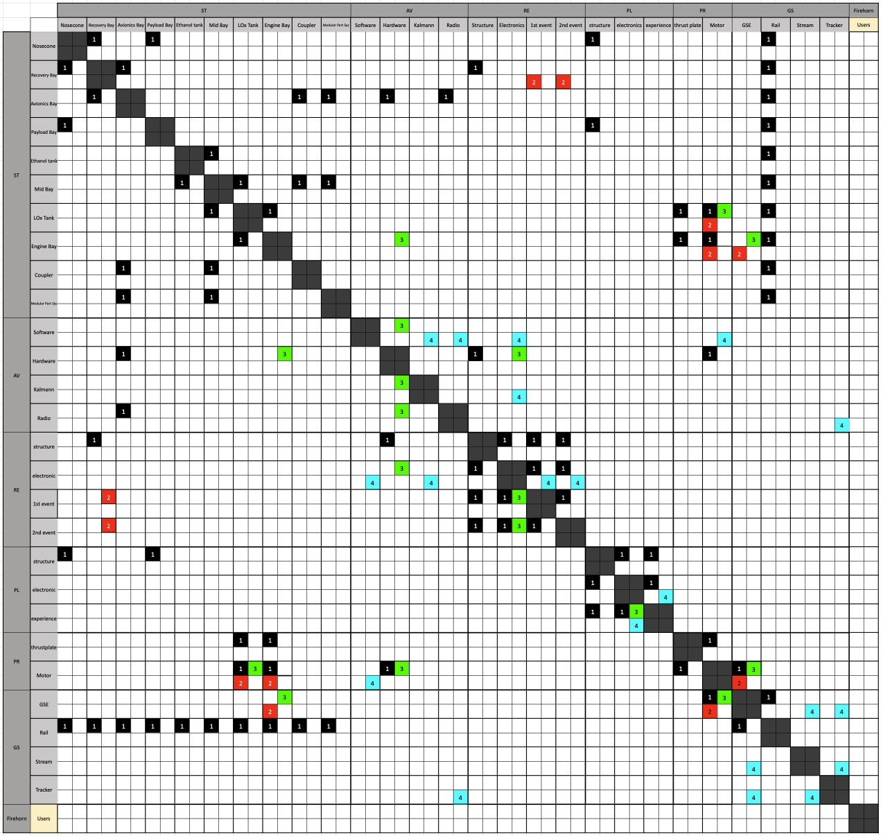
¶ High Level Interface Management
The high level interface management is critical in the development of complex systems to ensure good integration of the different subsystems.
We use a DSM to highlight how the different subsystems/assemblies/subassemblies/parts interface with each other in order to better sythesize and manage interfaces. This tool allows the team to have an identification that is as comprehensive as possible.
The high level DSM of the system is modeled as follows,
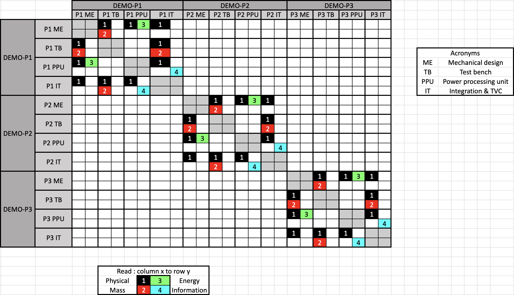
¶ Low Level Interface Management
To efficiently manage lower level interfaces, we need to identify all the assemblies that have interfaces between them. We used a DSM as well,
TO BE REPLACED
Once all the relevant interfaces have been identified, we establish a LLIM document that highlight the informations that have to be taken into account in the design on both of the concerned assemblies. This document follows the following format,
- Interface Description
- Diagrams
- Enumerated Interfaces
- Relevant Requirements
- Interface Verification Tests
- Relevant Documents
¶ Documentation
¶ Design Justification File
DJFs are part of the key elements that compose the documentation portfolio produced for the PDR. They provide a comprehensive description of the different concepts that were generated, and then how the tradespace was explored and which concept was selected. This file follows the following format,
- Introduction
- Relevant Knowledge Needed
- Design Options
- Narrowing the Design Options
- Detailed Design
¶ Multi-Physics Simulation Report
The MPSR is a document that allows to report and track the work being done on a specific simulation task while ensuring that both quality and consistency standards are met. This document aims to guarantee that all the neccesary assumptions are being documented and that results are displayed in a coherent manner.
¶ Design Definition File
The DDF is a document which establishes the system or product characteristics such as lower level technical specifications, design and interface description, drawings, electrical schematics, specified constraints (e.g. on materials, manufacturing, processes, and logistic).
¶ System Verification and Validation Methods
¶ Verification and Validation Plan
Verification Methods:
-
Testing: Perform various tests, including functional tests, environmental tests, and stress tests, to validate design performance under different conditions.
-
Simulation: Employ computer simulations to model and validate system behavior, predict performance outcomes, and identify potential design flaws.
-
Stakeholder Feedback: Gather feedback from stakeholders, and domain experts to verify design requirements.
Validation Methods:
-
Prototyping: Build prototypes or mock-ups of the system to validate design concepts, test functionality.
-
TVC Testing: Conduct tests in vacuum environment to validate a system and its dependencies.
Criteria for Success:
Clearly define criteria for success for each verification and validation method, including performance metrics, acceptance criteria, and threshold values. Ensure alignment with project objectives and stakeholder requirements.
¶ Test Procedures and Protocols
¶ Test Preparation
Each test is meticulously prepared, with detailed OP created and reviewed by experienced staff. Ensure that all necessary equipment, tools, and resources are available and properly calibrated before conducting the test.
¶ Test Execution
Follow the prescribed OP precisely, adhering to safety protocols and best practices throughout the test. Record all relevant data, observations, and measurements accurately during the test process.
¶ Verification and Validation Results
The results of verification and validation activities provide critical insights into the design's performance, functionality, and compliance with specifications and requirements. Through meticulous testing and evaluation, the following key outcomes are obtained:
¶ Verification Results
Confirmation of compliance with specified requirements, standards, and design criteria. Identification of any discrepancies or non-conformances between the design and the defined requirements. Validation of individual components, subsystems, and the overall system against predefined verification criteria. Documentation of verification test results, including test plans, procedures, and outcomes.
¶ Validation Results
Demonstration of the design's effectiveness, and suitability for its intended purpose. Assessment of the design's performance and functionality in real-world scenarios and environments. Identification of any issues or challenges encountered during validation testing and their resolution. Documentation of validation test results, including field test data, and validation reports. The verification and validation results serve as a basis for decision-making and design refinement, informing corrective actions and improvements to enhance the design's quality and reliability. By validating compliance with requirements, and verifying functionality and performance, the verification and validation process ensures the design's readiness for deployment and operation, ultimately contributing to the success of the project.
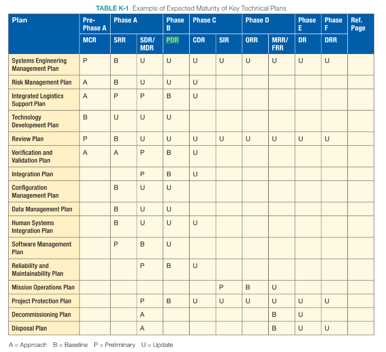
¶ Project Schedule
¶ Milestones and Deliverables
The main project milestones include the SRR, PDR, CDR, SIR, FRR and PFAR. These milestones are strategically positioned within the project lifecycle to ensure alignment with project management objectives and facilitate systematic progress toward project goals.
¶ System Requirements Review
The SRR marks a critical milestone in the project lifecycle, and as such, it necessitates the production of several key deliverables. These deliverables include the MSD, which outlines the overarching concept and objectives of the project, providing a high-level overview of its scope and purpose. The SEP details the approach and methodologies to be employed throughout the project, delineating roles, responsibilities, and processes. Additionally, the DRL and DRJ articulate the specific design requirements and their rationale, ensuring alignment with project objectives and stakeholder needs. Furthermore, the HLIM and LLIM document the interfaces between various subsystems and components, facilitating coordination and integration efforts. Together, these deliverables form the foundation for the SRR, providing the necessary documentation and guidance to evaluate the project's progress and readiness for further development stages.
¶ Preliminary Design Review
As the project progresses to the PDR stage, it mandates the comprehensive updating of all preceding documents to reflect the latest developments and insights gained throughout the project lifecycle. This includes revising and refining the MSD to incorporate any new findings, adjustments, or clarifications regarding the project's overarching concept and objectives. Similarly, the SEP undergoes thorough updating to ensure that the approach, methodologies, roles, and responsibilities remain current and aligned with evolving project needs.
In addition to updating existing documentation, the PDR necessitates the creation and presentation of the DJF. This file provides detailed rationale and justification for design decisions made during the preliminary design phase, elucidating the underlying principles, constraints, and trade-offs considered. It outlines the design requirements, specifications, and methodologies employed, demonstrating the rationale behind the proposed design solutions and their alignment with project objectives and stakeholder needs.
By updating and enhancing existing documentation while providing the DJF, the project team ensures transparency, accountability, and alignment with project goals, facilitating a comprehensive evaluation of the project's progress and readiness for the subsequent stages of development.
¶ Critical Design Review
As the project advances to the CDR stage, several essential deliverables must be provided to ensure the comprehensive evaluation of the design's readiness for implementation and manufacturing. These deliverables include:
- DJF: This document provides a detailed description of the design solution, including specifications, requirements, and architectural diagrams. It serves as a comprehensive reference for all aspects of the design, ensuring clarity and alignment with project objectives.
- DDF: The DDF is a document which establishes the system or product characteristics such as lower level technical specifications, design and interface description, drawings, electrical schematics, specified constraints (e.g. on materials, manufacturing, processes, and logistic).
- TD: TD, including schematics, diagrams, and blueprints, provide detailed representations of components, assemblies, and systems. These drawings serve as a reference for manufacturing, assembly, and maintenance activities, ensuring accuracy and consistency in implementation.
- MAP: This Manufacture and Assembly Procedure document outlines the procedures and guidelines for manufacturing and assembling components and subsystems. It includes step-by-step instructions, quality control measures, and safety precautions, ensuring consistency and reliability in production processes.
- TRP: The Test Report documents the results of verification and validation tests conducted on the design. It includes detailed test procedures, observations, findings, and conclusions, providing evidence of compliance with specifications and requirements.
These deliverables collectively demonstrate the maturity, completeness, and readiness of the design for implementation and manufacturing, facilitating informed decision-making and ensuring the success of the project.
¶ System Integration Review
As the project transitions to the SIR phase, the focus shifts towards ensuring the seamless integration and operational readiness of the system. Key to this phase is the production of comprehensive operations procedures, which serve as a guide for the effective deployment, operation, and maintenance of the system.
OP encompass a wide range of activities, including system setup, startup/shutdown procedures, routine operations, troubleshooting, and maintenance tasks. These procedures are meticulously documented to provide clear instructions for operators, technicians, and maintenance personnel, ensuring safe and efficient system operation.
¶ Flight Readiness Review
At this step of the project, all components have been verified as they were intended to and successful integration of all subsystems has been conducted. The FRR is proceeded by the EuRoC Staff in the case of Firehorn I and the results will determine whether the launch vehicle can safely operate in flight conditions.