¶ Electrical Cabinet Documentation
¶ 1. Introduction
This document is intended to help members of the association understand how the electrical cabinet is structured and how it works. It is written with accessibility in mind, and is not directed to seasonned electricians.
It explains the context of the electrical clostet, and how each individual component inside of the electrical works, and details the wiring inside of the closet using a few examples.
It is focused on the electrical closet inside of the ERT's Test container, and does not go over the power distribution and security at the whole testing facility scale.
This file shall be kept up to date as the electrical closet is modified and/or updated.
¶ Abbreviations
TC Test container
ERT EPFL Rocket Team
CC control container
¶ Applicable Reference documents
-
2024_H_TF_ELEC_DDF Description of the Control Container's high power (230V) electrical circuit
-
2025_H_TF_ELEC_CLOSET_DDF Listing of the elements inside the Testing Facility's electrical closet
-
2024_H_TF_ELEC_EMERGENCY-STOP Description of how the emergency stop wiring works
-
2024_H_TF_PLUMBING_DDF Description of the Testing Facility's plumbing layout
¶ 2. Overview General Context
The Electrical closet is located inside of the Test container.
It powers and controls most equipment needed for engine tests, mainly:
- Valves, located in the plumbing and engine area
- Status LEDs located on the container's roof for signaling and safety purposes
It receives a single-phase 230 V AC feed and delivers several 24 V DC and 5 V DC rails inside.
¶ 3. Individual Compponents List and description
The power supplies convert the 230V AC into DC. We have one 5V DC power supply, and multiple 24V DC which is required by most components in the cabinet.
It receives 230V AC on its input terminals, usually marked L (live), N (neutral), and PE (ground). On the output side, it provides +24/5V and 0V, which is then routed to the rest of the system.
The DC voltage is distributed through Wago connectors located further up the cabinet. These connectors make it easy to connect multiple devices to the same power source.
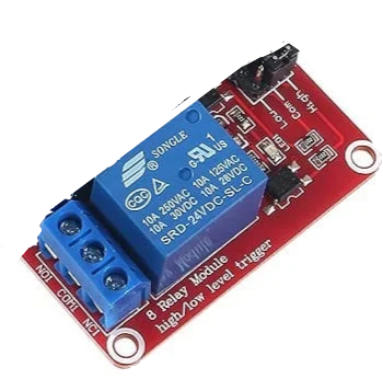
This cabinet uses 3 8-channel relay modules. Each blue block is an electromechanical relay mounted on a red circuit board. The modules allow low-voltage signals (from the PLC or another controller) to switch higher-power devices like valves.
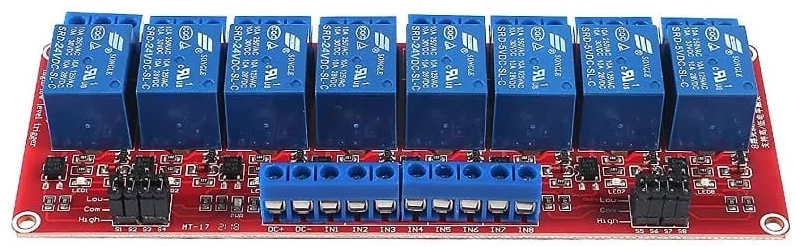
Each relay (blue bloc) has:
- Three screw terminals at the top:
- COM (common): power input, where the 24V and current comes in
- NO (normally open): only connects to COM when the relay is active
- NC (normally closed): not used in our setup
We never use the NC terminal , so by default, no current flows to the connected device. Power only passes through when the relay is activated, which is safer.
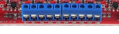
At the bottom of the module:
- There are individual signal inputs (IN1, IN2, ..., IN8)
- 24V- (DC-) and 24V+ (DC+) terminals provide power to the relay board
When a signal (e.g. 24V from the PLC) is sent to a relay signal input, say, the corresponding relay switches, connecting it's COM and NO, allowing current to flow to the connected device.
¶ LED Indicators:
- A green LED on the board shows that the relay board is powered.
- Each relay has a red LED that lights up when the relay is active (i.e., when COM and NO are connected).
These visual indicators are very helpful for checking that everything is working correctly during testing or debugging.
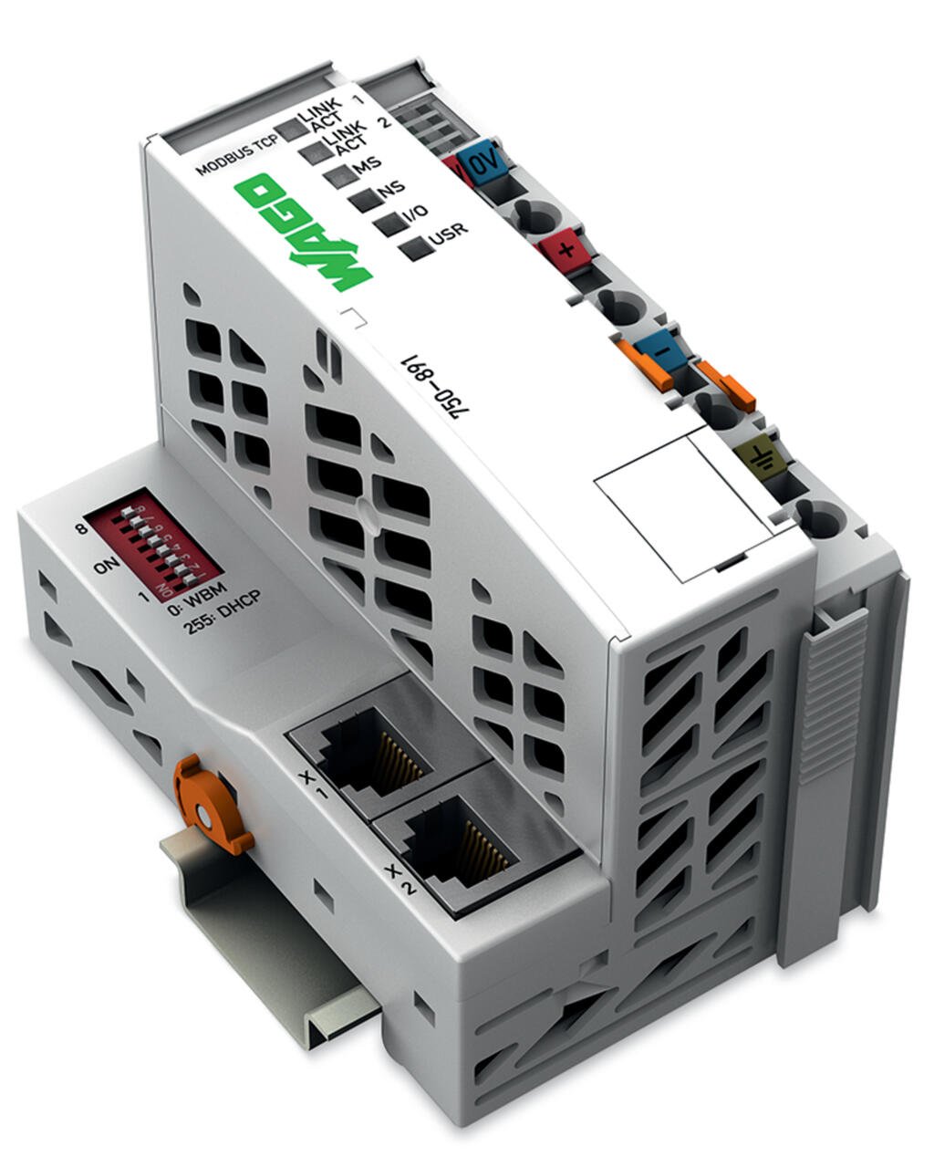
| - The WAGO PLC 750-8111 (Programmable Logic Controller) is the brain of the cabinet. It’s a small industrial computer that is controlled via the graphic interface on the CC's computer, and controls outputs (like relays or actuators) according to a program.
It is powered by 24V DC, like most of the components in the system. The base unit (the controller) can be extended by plugging in different I/O modules on the side, which all communicate through a shared internal bus. These modules are controlled directly by the PLC. |
||
|
|
|
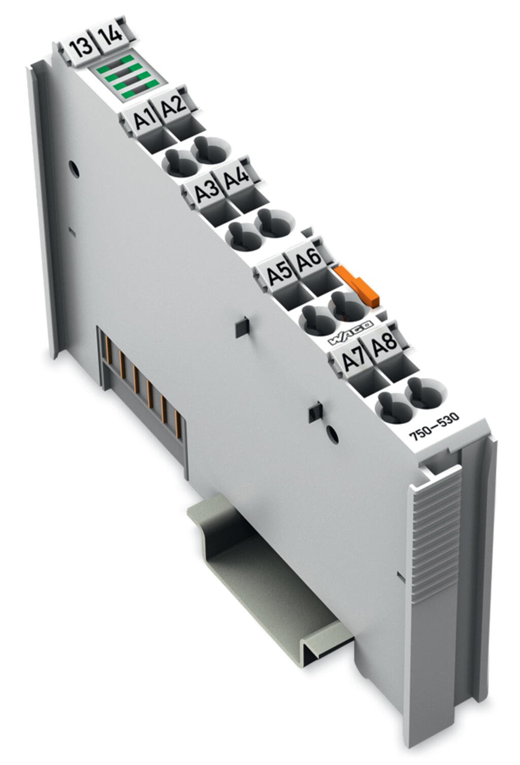
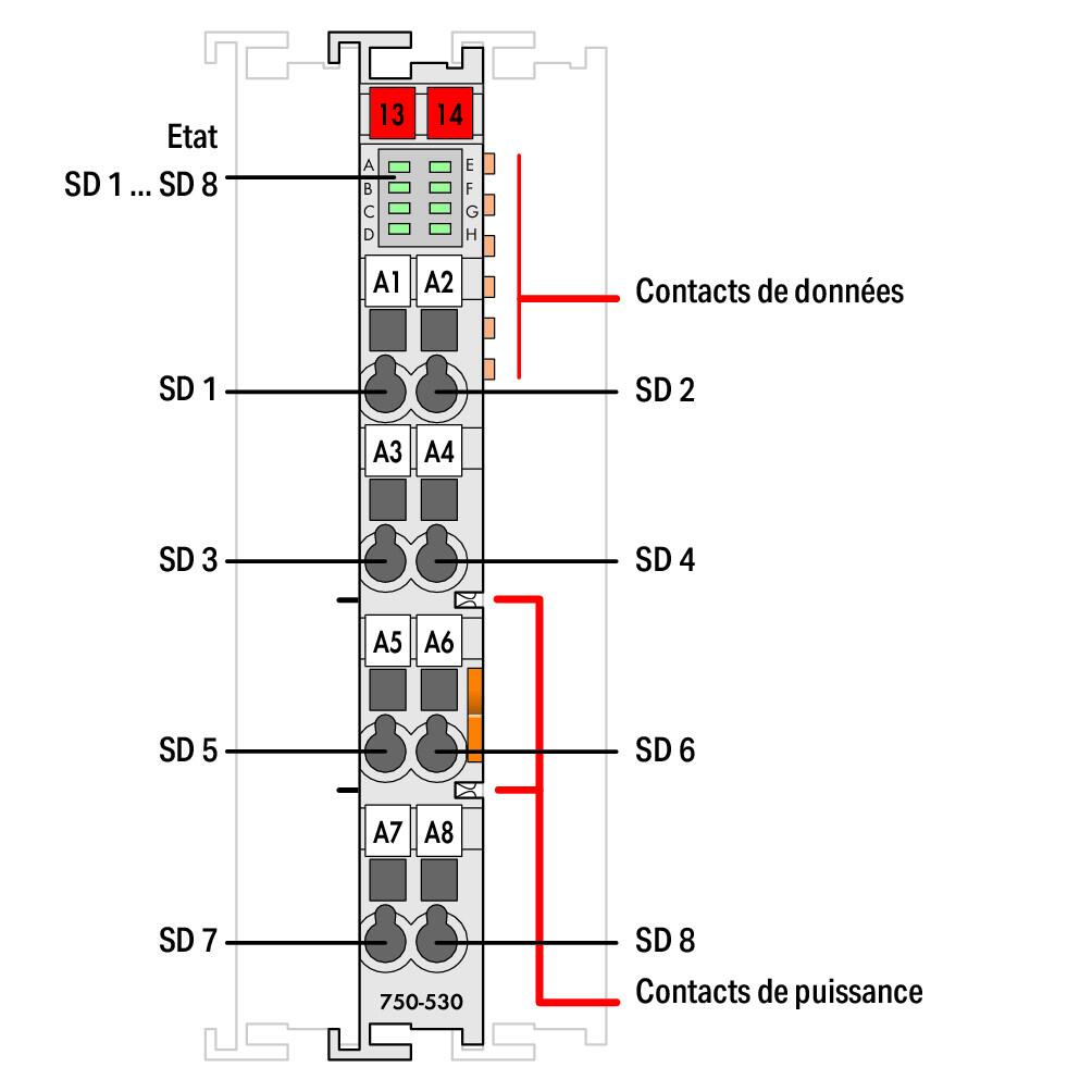
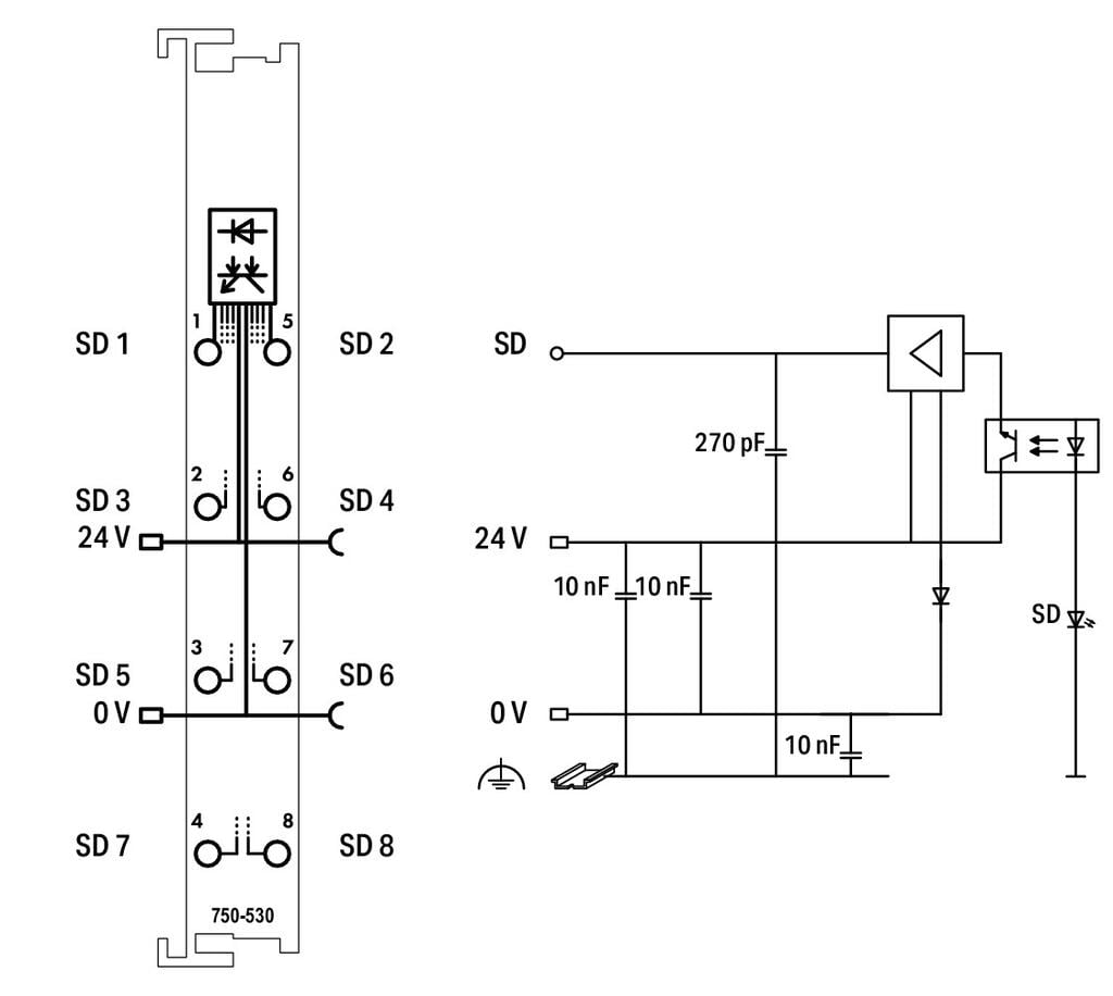
| We use 8 channels 24V digital output modules 750-530 which send 24V signals (used to control relays). These modules provide **signal voltage**, but not much current — they are not meant to power devices directly. On the module, an active port is indicated by a green light. F.e if the green light on top labeled E is turned on, it means the A2 port is active and sends out 24V. | ||
|
|
|
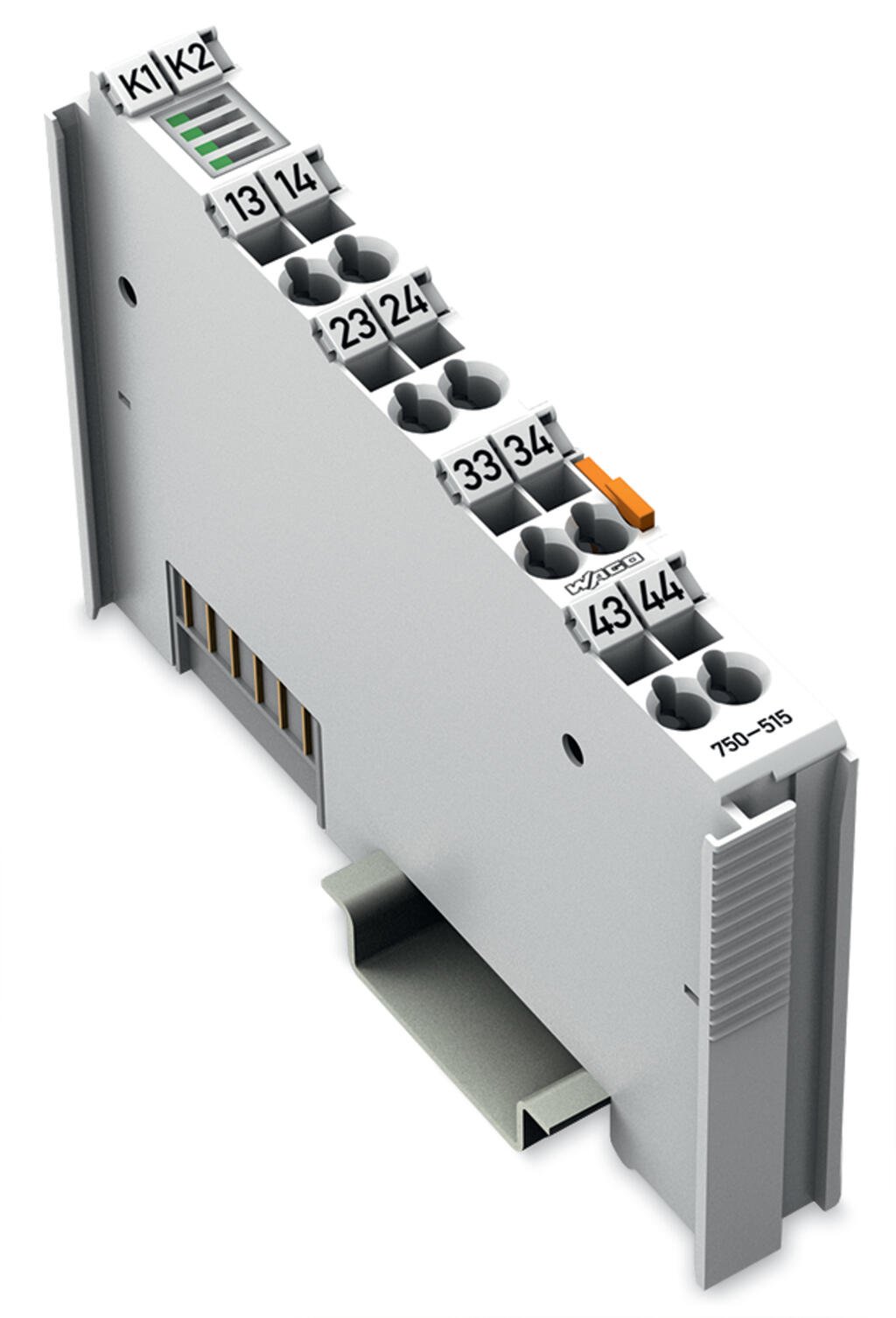
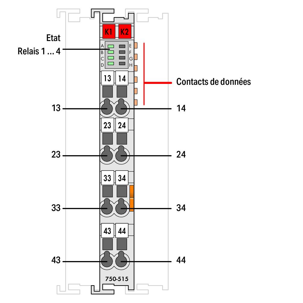
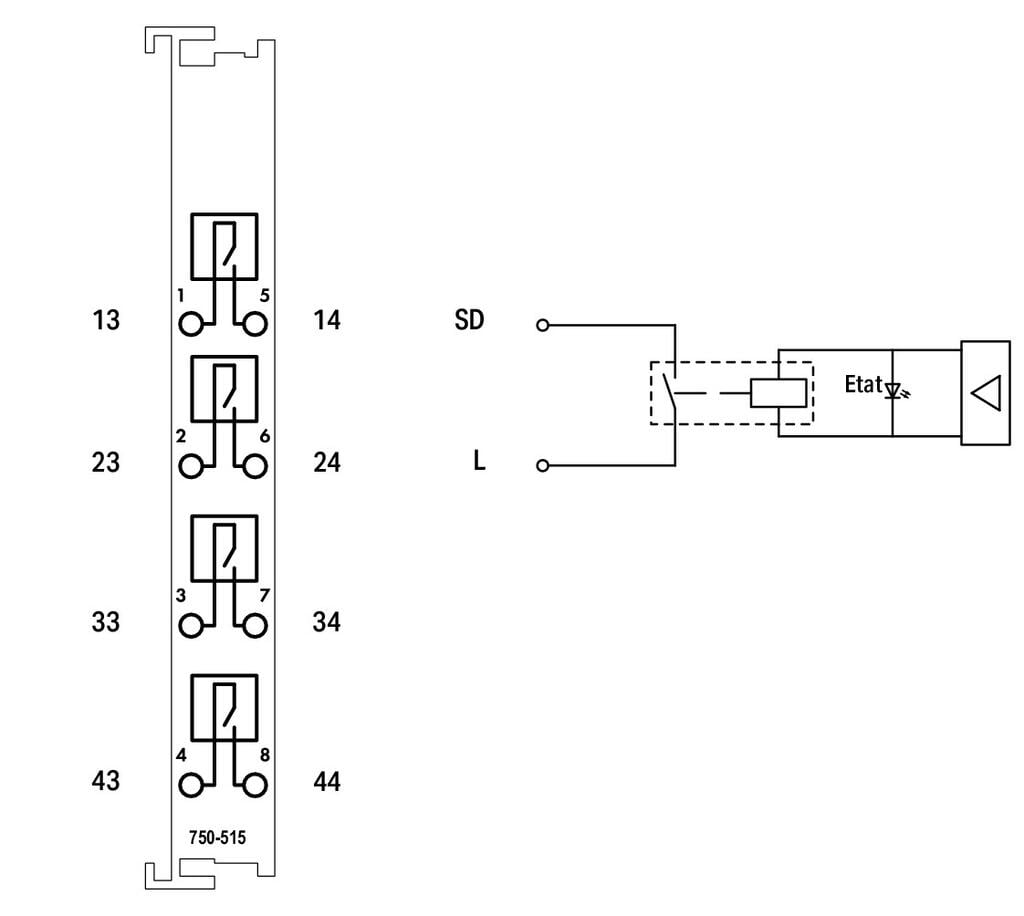
| We also use 230V output modules 750-515 These modules act like integrated relays and can directly switch 230V AC devices (like the LEDS on the exterio of the container). This removes the need for a separate relay in some cases.On the module, an active relay is indicated by a green light. F.e if the green light on top labeled C is turned on, it means the third relay from the top, A3 - A4 is closed, lets the 230V trhough.. | ||
|
|
|
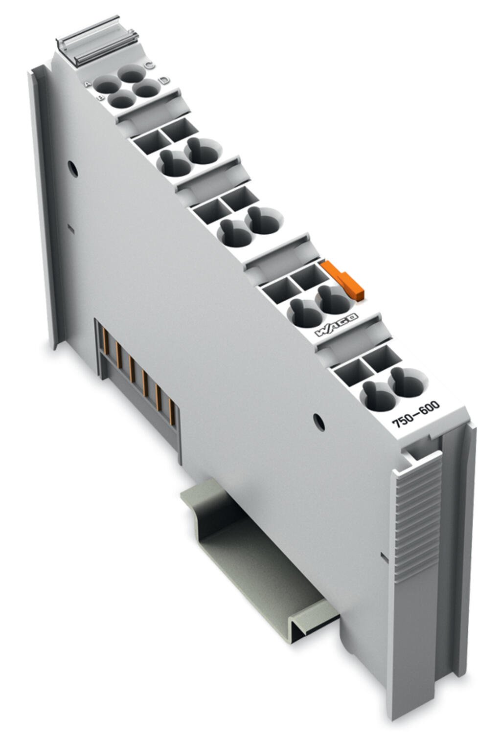
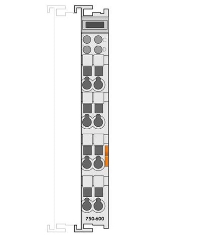
| And an End module 750-600 which is an inert module that needs to be used as the last module in a row, to close off the bus. | ||
|
|
|
| Additionaly we have a 16 channels 24V digital output module 750-1605 | ||
| And a 16 channels 0V digital output module 750-1606 | ||
The system is modular: WAGO offers a huge variety of extension cards — for analog signals, PWM, stepper motor control, communication protocols (Ethernet, Modbus...), and more. These modules are powerful but can also be quite expensive.
For most of our needs, the PLC sends 24V signals to trigger relays, which then switch the actual power to devices.
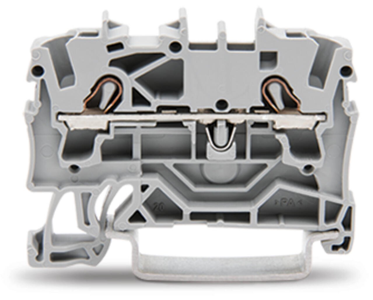
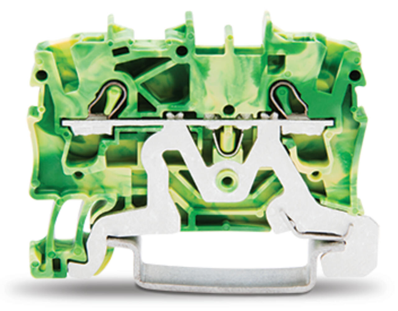
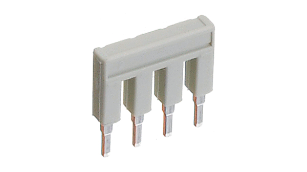
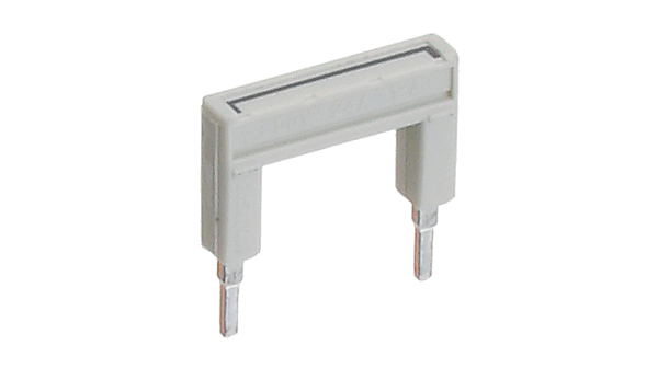
The small colored modules on the DIN rail are WAGO terminal blocks, all similar to this one. They are used to securely connect wires inside the cabinet while keeping everything organized and easy to maintain.
|
|
Each terminal has:
- Two openings for wires: one at the top and one at the bottom.
- A slot for a flathead screwdriver next to each wire opening. When pressed, it opens the internal clamp so you can insert a wire. Releasing the screwdriver locks the wire in place. The top and bottom entries are electrically connected.
This setup is ideal for routing power or signals between components in a clean and reliable way.
You can link multiple of these terminal blocs together using WAGO jumper bars, which are inserted into the small holes in the middle of each block. This allows:
-
Side-by-side connections to distribute power across several terminals
-
Or long-distance connections using longer jumpers to reach across the DIN rail
We try to follow a consistent color code for these terminals:
- Black for 230V AC
- Grey for 24V DC positive
- Blue for AC neutral, and 24V neutral
- Green-yellow for earth (ground)
The earth terminals (green-yellow) also make contact with the metal mounting bar they are clipped onto, which grounds them directly. However, the cabinet itself is grounded separately to ensure the overall structure is safely earthed.
The emergency stop (E-Stop) system is wired through a contactor, which is a special type of relay designed for switching high-power circuits. It acts as a master on/off switch for the entire system.
When the emergency switch is pressed, it cuts the power supply to the contactor’s coil, causing the contactor to open and shut off power to everything downstream — including the 24V and 230V circuits.
What's important (and maybe confusing at first) is that once power has been cut, whether by pressing an E-Stop or through another fault, releasing the E-Stop does not automatically turn the system back on. You also have to manually press the contactor reset button (or toggle a dedicated reset signal) to re-energize the coil and restore power.
This is intentional. It prevents the system from restarting on its own after an emergency — which could be dangerous. You must explicitly confirm that the system is safe to power back up.
The contactor is wired with a self-hold circuit, sometimes called a "latching loop". This ensures that:
- Power stays on as long as the coil is energized and the safety loop is intact
- If the emergency stop is pressed, the loop is broken
- To re-latch the contactor, you must press a reset button, which momentarily re-energizes the coil
This design is standard in industrial safety systems. For details on how the wiring works, you can refer to
Inside the cabinet, we use a variety of cable and wire types depending on the function, voltage, and current.
Most power and signal cables are three-core flexible wires, typically color-coded as red, blue, and green-yellow. Sometimes you'll see cables with labels like 1, 2, or green-yellow, which are often used for control lines (e.g. valve commands).
Thicker cables are used for high-power parts of the system — especially for 230V AC lines or main valves that draw more current. These must be sized appropriately to avoid overheating.
Inside the cabinet, connections between terminals or components are made using crimped flexible wires. These provide a secure and clean way to insert flexible wires into screw terminals. For multi-stranded wires, we always use ferrules at the ends to prevent stray strands and ensure reliable connections.
For sensitive components such as sensors or data lines, we use shielded cables. These help reduce electrical noise and interference from nearby power cables or relays.
All internal wiring uses flexible cables suitable for DIN rail environments, with appropriate insulation and cross-section based on current and safety.
¶ 4. Power Distribution Example: How the Closet Powers One Valve (PN)
This section explains how power is distributed inside the closet, using one random example: the valve "PN". The goal is to show the main path of the phase (live 230V) and how it gets converted and routed to a final actuator.
¶ 1. 230V Input and Protection
The 230V AC power enters the closet and connects first to the main input WAGO terminal blocks at the top. From there, the 230V live wire (phase) goes through:
- The emergency stop switch (E-Stop), which can immediately cut off power if needed
- The contactor, which acts as a master relay for safety control
After passing through the E-Stop and the contactor, the 230V line returns to the top WAGO terminals. At this point, the closet is "armed," and the 230V is ready for distribution.
¶ 2. 230V Distribution to Power Supplies
From the top 230V terminals, the phase is routed down to the power supplies located at the bottom of the closet:
- Each power supply receives its own 230V live, neutral, and earth connections.
- For this example, we only focus on the 24V DC power supplies used for valve control.
The 24V DC outputs of the supplies are combined (put in parallel) and routed back up to a set of middle grey WAGO terminal blocks, which serve as the distribution point for 24VDC across the system.
¶ 3. 24VDC Distribution
From the middle grey WAGO blocks, the 24V DC power is distributed to:
- The WAGO PLC (to power its electronics)
- The relay boards (to energize relay coils)
- The COM pins of each relay associated with a valve circuit
Specifically for valve PN:
- The 24VDC is connected to the COM pin of the corresponding relay on the relay board (right block).
- Another 24VDC wire connects the IN1 input port of the relay board to the corresponding digital output of the WAGO PLC. This input controls the first relay channel, associated with the PN valve.
- Additionally, a 24VDC wire connects the NO1 terminal (Normally Open contact) of the relay to the grey WAGO terminal block dedicated to the PN valve output at the top of the closet.
¶ 4. Controlling the Valve
When the relay associated with PN is activated:
- The 24VDC passes through the Normally Open (NO) contact of the relay.
- It is then routed to the grey WAGO terminal block connected to the PN valve.
In this way, the PN valve only receives power when explicitly commanded, ensuring safe and controlled operation.
This example shows how high-voltage AC is safely converted into low-voltage DC, then routed through protection and control elements before reaching the final actuator (the valve).