¶ Introduction
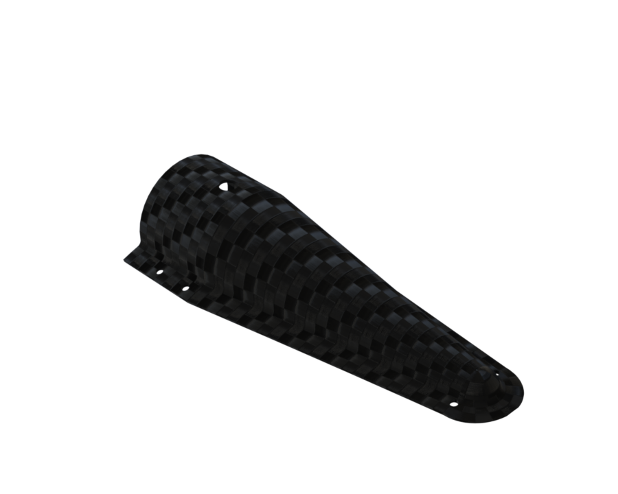
The Aerocover is a structural component designed to protect external plumbing elements, such as cables and tubing, located on the exterior of the rocket.
.png)
This document aims to inform the Rocket Team, about the technical definition of the Aerocover. It outlines the design, material selection, assembly method, and interfaces, ensuring that the component meets all required functional and structural criteria.
Simulations, infusion technique, and design validation will not be addressed in this document.
¶ Applicable and Reference Documents
The documents listed below provide additional context to the technical definition of the Aerocover.
- 2025_C_ST_INFUSION_MAP
- 2024_C_ST-PR_LLIM Structure / Propulsion Low Level Interface Management
For more information on the design, here is a document describing the entire PDS reflection process and the different manufacturing options available to us :
¶ Requirements
¶ Aerocover Requirements
- 2024_C_SE_ST_AEROCOVER_REQ_01 Aerocover declaration of purpose
The aerocover shall reduce the drag of all plumbing and electrical elements located outside of the LV and between the pressurant bay and the mid bay. - 2024_C_SE_ST_AEROCOVER_REQ_02 Aerocover structural mass
The structural mass of the aerocover shall not exceed [1000]g. - 2024_C_SE_ST_AEROCOVER_REQ_03 Aerocover length
The aerocover shall extend from the pressurant bay to the engine bay. - 2024_C_SE_ST_AEROCOVER_REQ_04 Aerocover aerodynamic profile
The aerocover aerodynamic profile shall minimize the drag added on the LV. - 2024_C_SE_ST_AEROCOVER_REQ_06 Aerocover camera integration
The aerocover shall incorporate a camera on either extremities. - 2024_C_SE_ST_AEROCOVER_REQ_08 Aerocover fixation load case
The aerocover fixations shall support an axial deceleration of the aerocover and elements fixed to it of [600] m/s².
¶ Interfaces
The Aerocover assembly interfaces primarily with the following rocket subsystems:
¶ Interface AV
- ⬛Physical interface:
It is designed to protect the avionics cables that run from the pressurization bay to the engine bay, passing through the outside of the fuselage and tanks.
¶ Interface PR
- ⬛Physical interface:
It is designed to protect the PR tubes that run from the Pressurization_bay and Mid_Bay to the Enigne_Bay, passing through the outside of the fuselage and tanks.
¶ Interface PL
- ⬛Physical interface:
The design of the aerocover must be compatible with the end caps designated by the payload subsystem to support cameras at both ends.
¶ Overview
The Aerocover is a structural protective assembly designed to shield external plumbing components such as cables and tubes on the rocket’s exterior between the Pressurant_bay and Engine_Bay.
It consists of three main composite parts that are assembled together through carbon fiber layup infusion from the inside.
The descriptions of the two different parts can be found below.
The reasoning behind the choice of form can be found in this document.
The choice of the first form was retained for reasons of ease of manufacturing.
¶ Main Specifications
| Specification | Value | Unit |
|---|---|---|
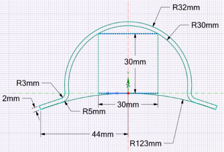
| Dimensions | 1500x 40 x 30 | [mm] |
| Weight | 500 | [g] |
| Cost | 400 | [CHF] |
¶ Parts Descirption
¶ Description
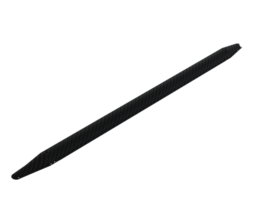
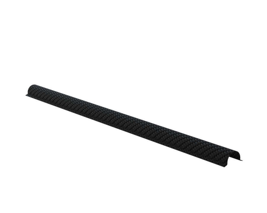
- Three Composite Sections: These form the primary structure of the Aerocover, each fabricated from carbon fiber composite using vacuum infusion techniques. The parts are joined to create a continuous protective shell approximately 2.5 meters in length.
¶ Description
-
Two Closing Plumbing Covers: Located on each side of the assembly, these covers provide access points to the plumbing system while maintaining aerodynamic integrity and protection. This time we used prepreg technique.
-
The design was produced by the Payload subsystem; therefore, these parts are considered Payload components.
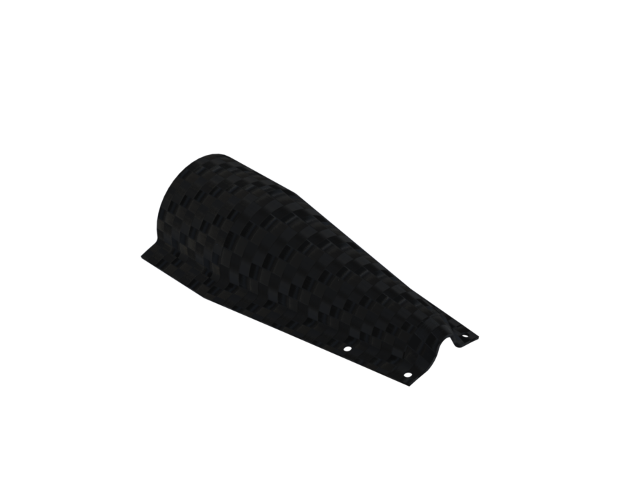
- The first end cap is the bottom one, allowing the camera to film downward.
- The second end cap is the top one.
¶ Interface
Interface PL-ST
- ⬛Physical interface:
The end caps have side screw holes to attach onto two MPS units: one in the Pressurant_Bay and one in the Engine_Bay.
¶ Technical Budget, Margins and Deviation
| Type of value | Units | Requirement Value | Actual Value | Deviation |
|---|---|---|---|---|
| Dimensions | mm | 1500x 40 x 30 | 1500x 40 x 30 | 0 % |
| Weight | g | 1000 | 500 | -50% |
¶ Design Constraints
¶ Production
- Built with vacuum-infused carbon fiber.
- Three composite parts must be precisely aligned and bonded.
- Assembly order is critical to avoid curing issues or misalignment.
- Two plumbing covers must be installed to keep sealing and aerodynamics.
¶ Operation
- Handle carefully to avoid deformation or impact damage.
- No direct hazards for operators, but requires cautious management.
¶ Other
- Store in dry, temperature-controlled conditions to prevent moisture.
- Length (~2.5 m) requires adapted transport and protective packaging.
- Reusable if post-flight inspection shows no damage.