¶ Introduction
Rocket fins play a vital role in the stability and control of rockets during flight. These aerodynamic surfaces are typically located at the tail end of the rocket and are designed to generate forces that counteract any unwanted motion, such as roll, pitch, or yaw. Fins provide stability by creating aerodynamic forces that help maintain the rocket's desired trajectory and prevent it from veering off course.
This Design Definition File (DDF) aims to present the specifications of the fins from a structural design perspective.
¶ Applicable and Reference Documents
¶ Requirements
- 2024_C_SE_ST_ENGINE-BAY_REQ_08 Fins fixation
The engine bay shall allow for the fins fixation along the entire length of the fin base. - 2024_C_SE_ST_ENGINE-BAY_REQ_18 Fins loads bearing - Axial force
The fins fixation points shall withstand axial forces caused by the fins of up to [600]N. - 2024_C_SE_ST_ENGINE-BAY_REQ_19Fins loads bearing - Bending moment
The fins fixation points shall withstand bending moments caused by a force of [5000]N applied perpendicular to the fins main surface. - 2024_C_SE_ST_ENGINE-BAY_REQ_20FH I fins first bending mode
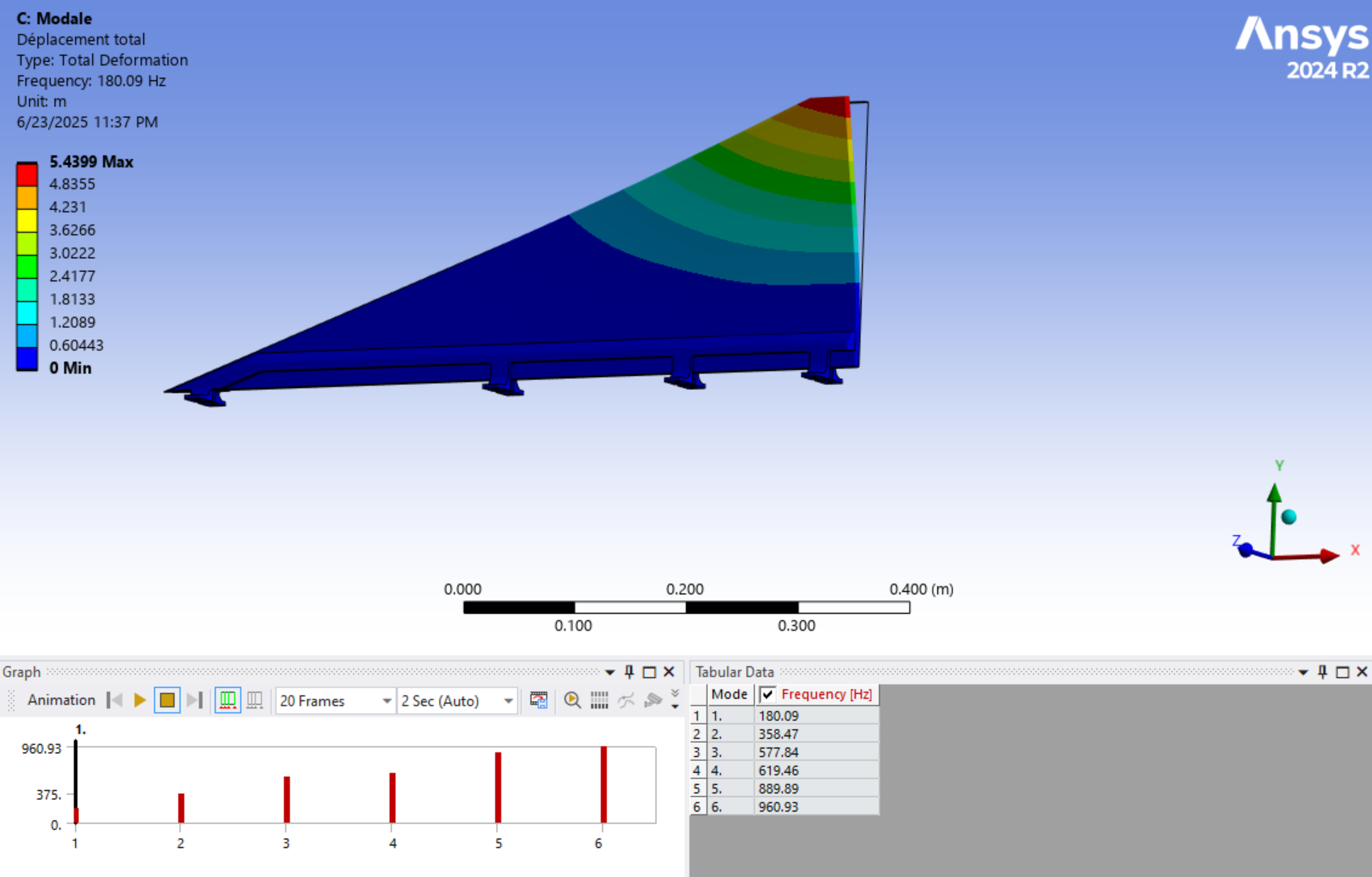
The FH I fin and clamp assembly shall have a first bending mode eignefrequency of above 180[Hz]. - 2024_C_SE_ST_ENGINE-BAY_REQ_21FH I fins first torsional mode
The FH I fin and clamp assembly shall have a first torsional mode eignefrequency of above 220[Hz]. - 2024_C_SE_ST_ENGINE-BAY_REQ_24FH I modal frequencies
The FH I fin and clamp assembly shall have at least 35[Hz] between the first bending mode and the first torsional mode eigenfrequencies.
¶ Overview
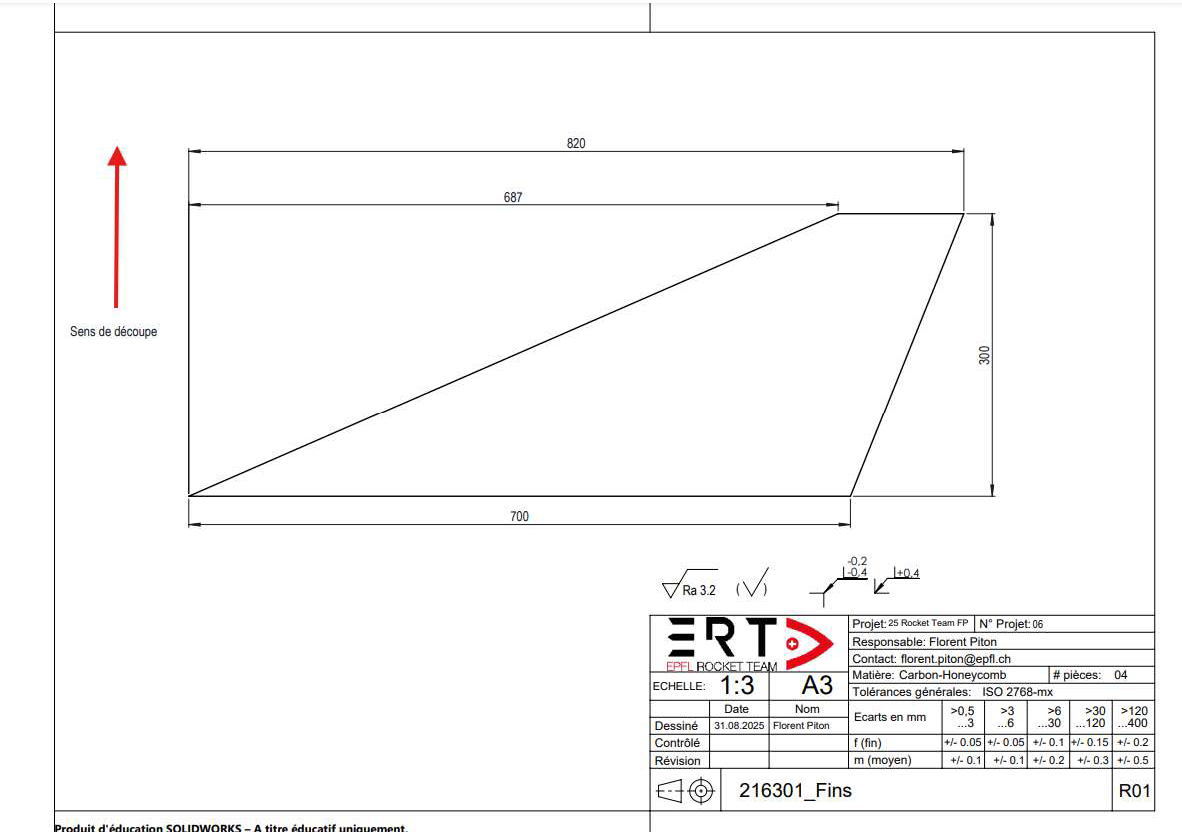
¶ Main Specifications
| Specification | Value | Unit |
|---|---|---|
| Root chord | 700 | [mm] |
| Tip chord | 133 | [mm] |
| Height | 300 | [mm] |
| Sweep length | 68.7 | [mm] |
| Sweep angle | 66.4 | [°] |
| Materials | Sandwich CFRP / Al-7075 | |
| Manufacturing | Prepreg / 5-axis CNC |
¶ Parts
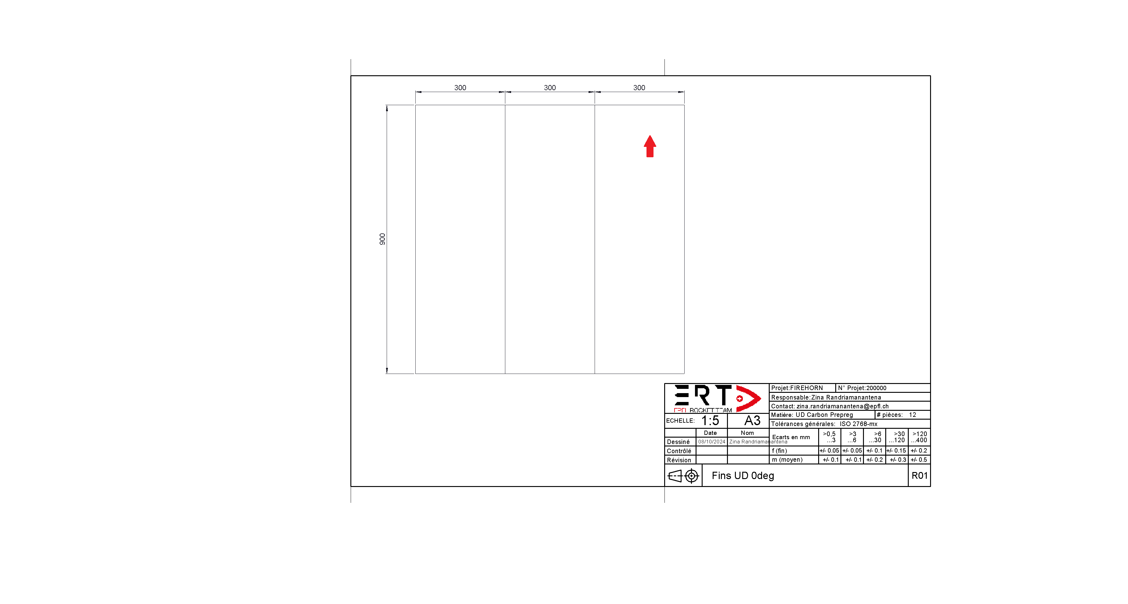
¶ Fins
| Denomination | Prepreg | Type | Thickness [mm] |
|---|---|---|---|
| EH25/34%/UD136/HTA-12K | UD | 0.14 | |
| w | W3T-282-42'-F593-14 | Plain | 0.24 |
| C | ECA C2-3.2-29 (aramid) | Honeycomb | Variable |
Due to time constraint with the supplier, the Fins-Plate (bulk material) for the fins was manufactured way before the definition of the load requirements and final geometry.
So, a flutter analysis using AeroFinSim was done to define the lay-up of the Fins-Plate. Arbitrary margins, informed by previous research, were taken into account during decision-making.
¶ Geometry
| Parameter | [cm] | [inch] |
|---|---|---|
| Root | 70 | 27.56 |
| Tip | 4 | 1.57 |
| Height | 24 | 9.45 |
| Sweep | 65.9 | 25.94 |
| Media | 24.3 | 9.57 |
¶ Material
| n° | Lay-up | Thickness [mm] | Thickness [inch] | Modulus [MPa] | Modulus [psi] | Poisson | Strength [MPa] | Strength [psi] | Density [kg/m³] | Density [lb/in³] |
|---|---|---|---|---|---|---|---|---|---|---|
| A | (0w(0.45w,0)2,0w,C3)SO | 6.03 | 0.24 | 64120 | 9297400 | 0.292 | 359.1 | 52069.5 | 745 | 0.02691 |
| B | (0w(0.45w,0)3,0w,C2)SO | 6.07 | 0.24 | 72600 | 10527000 | 0.344 | 479.26 | 69492.7 | 985 | 0.03559 |
| C | (0w(0.45w,0)3,0w,C3)SO | 7.07 | 0.28 | 69720 | 10109400 | 0.344 | 411.46 | 59661.7 | 850 | 0.03071 |
| D | (0w(0.45w,0)4,0w,C3)SO | 8.10 | 0.32 | 72940 | 10576300 | 0.38 | 448.42 | 65020.9 | 928 | 0.03353 |
¶ Results (sea level)
| n° | Thickness [mm] | Core [mm] | 2D-Lift Divergence [MACH] | 2D-Lift Flutter [MACH] | 3D-Barrowan Divergence [MACH] | 3D-Barrowan Flutter [MACH] | NACA TN 4197 Divergence [MACH] | NACA TN 4197 Flutter [MACH] | Theodorsen U vs g Divergence [MACH] | Theodorsen U vs g Flutter [MACH] | Crit. Freq. [Hz] | Bending [Hz] | Torsion [Hz] |
|---|---|---|---|---|---|---|---|---|---|---|---|---|---|
| A | 6 | 3 | 1.14 | 1.55 | 2.73 | 3.72 | 1.27 | 1.05 | 1.39 | 0.63 | 188.2 | 158.7 | 197.1 |
| B | 6 | 2 | 1.19 | 1.62 | 2.85 | 3.88 | 1.32 | 1.10 | 1.45 | 0.63 | 180.0 | 146.9 | 178.8 |
| C | 7 | 3 | 1.47 | 2.00 | 3.52 | 4.78 | 1.63 | 1.36 | 1.79 | 0.77 | 211.5 | 180.8 | 219.9 |
| D | 8 | 3 | 1.81 | 2.46 | 4.33 | 5.89 | 2.02 | 1.67 | 2.20 | 0.94 | 234.0 | 202.2 | 242.5 |
¶ Interpretation (worst values)
| n° | Divergence [MACH] | Flutter [MACH] |
|---|---|---|
| A | 1.14 | 1.05 |
| B | 1.19 | 1.10 |
| C | 1.47 | 1.36 |
| D | 1.81 | 1.67 |
¶ Definitive lay-up
0w(0.45w,0)3,0w,C2)SO h = 6.068 mm
The Fins-Plate is cut using water-jet cutting.
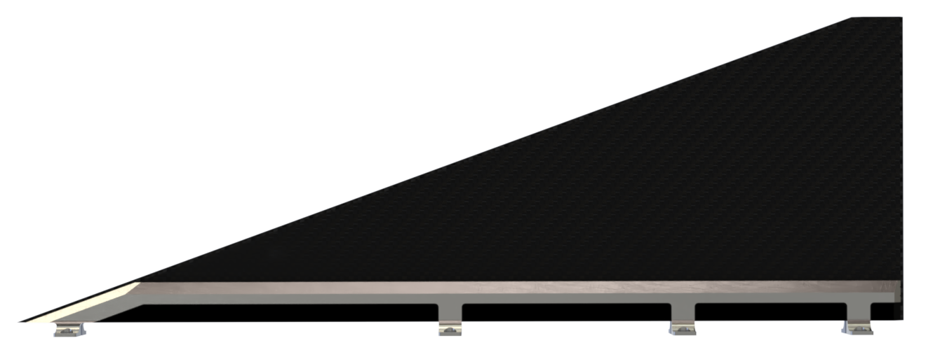
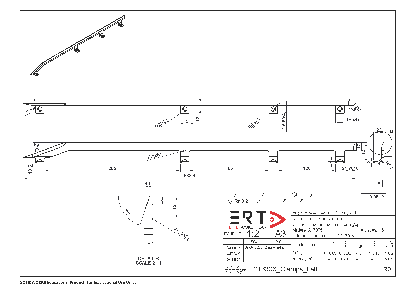
¶ Clamps
Clamps were designed way after the manufacturing of the Fins-Plate. The rationale was to adjust the clamps to comply with the final fin flutter requirements.
Ansys was used to simulate the natural frequency of the fin assembly.
An almost linear relationship was discovered between the clamp height and the first natural frequency
Therefore, the glued part to the fin was raised to maximize the stiffness while minimizing the clamp mass.
The gap between the clamp and the root chord is covered by 3D-printed spacers.
¶ Design Constraints
¶ Constraints for Production
Load requirements and final geometry were finalized in the project’s last phase.
Thereofore, the design and manufacturing of the fins had to include consequent margins.
The fins-plate was cut to its final geometry once the flight simulation became representative, i.e., using the accurate mass and length of the vehicle.
The clamps have a very high length to width ratio, complicating the machining.
Workshops reported the risk of elastic springback, resulting in a deflection of about 3-5 mm.
Nonetheless, in this case this deformation is not significative as the clamps are tightly glued to the fins.
¶ Constraints for Operation
The fins are bolted to the rods once the propulsion sub-system is done with the plumbing system.
In other words, the fins are integrated at the end of the paddock operations.
¶ Other Constraints
As the fins are made of honey-comb, the edges need to be filled with a joint or glue.
In this case, the edges were filled with 3M dp490.