¶ Introduction
This document presents the design and the engineering process behind the conception of the rocket fins and their clamping systems for the Firehorn rocket.
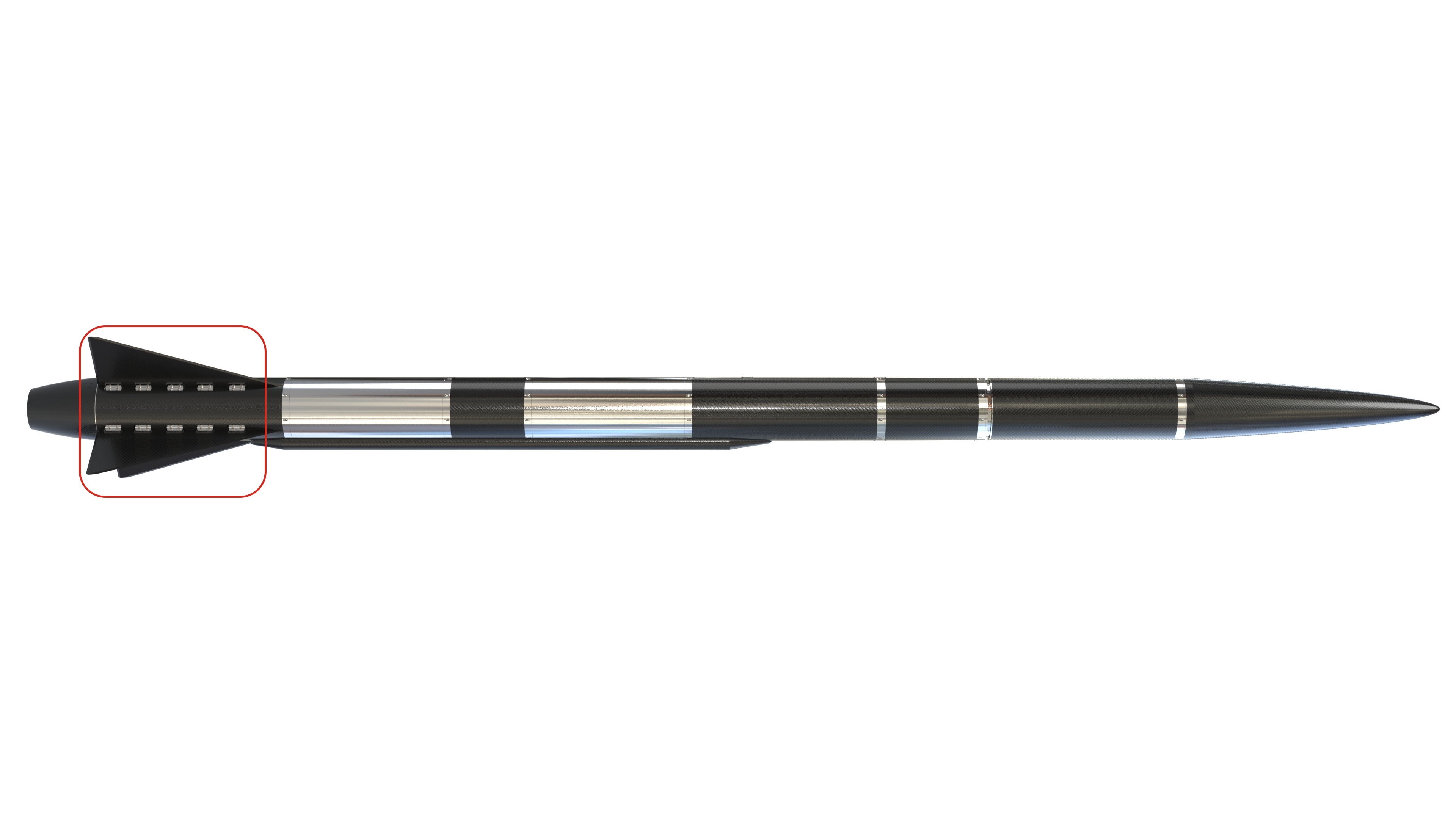
The fins are mounted on the rods of the Engine-Bay in order to guarantee the radial access.
¶ Definitions and Abbreviations
- ABV : Abbreviations
- FoS : Factor of security
- MoS : Margin of security
¶ Applicable and Reference Documents
¶ Requirements
- Fins loads bearing - Axial force
The fins fixation points shall withstand axial forces caused by the fins of up to [600]N.
- Fins loads bearing - Bending moment
The fins fixation points shall withstand bending moments caused by a force of [5000]N applied perpendicular to the fins main surface.
¶ Interfaces
- 2024_C_ST_PR_LLIM Structure / Propulsion Low Level Interface Management
¶ Parts Description
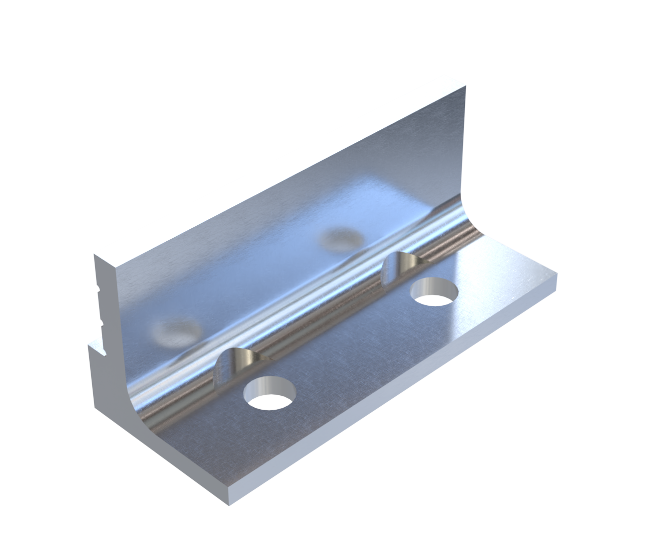
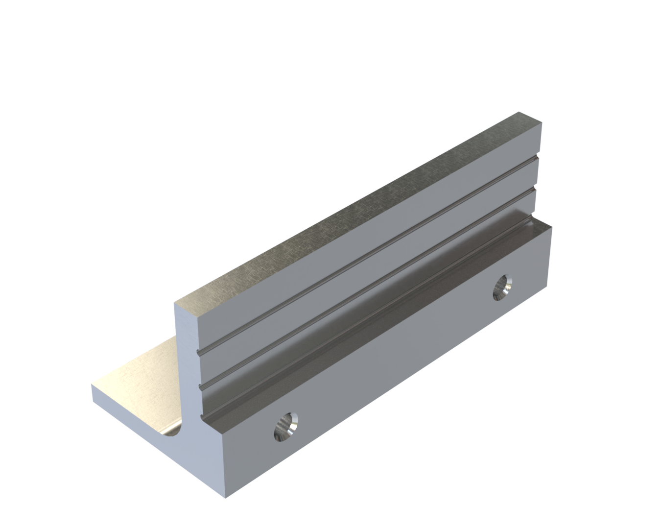
¶ 216302_Clamps
¶ Main Specifications
¶ Description
The clamp is made by 2 parts assembled together using pins and they're fixed to the rod.
| Part Name | Number of Parts | Main Characteristics | Link to .SLDPRT file |
|---|---|---|---|
| 216302_Clamp | 40 | Max dimensions : 25 x 25 x 56 [mm] | 216302_Clamp.SLDPRT |
¶ Interfaces
The clamp will be glued to the fin and it will be assembled to the rod by 2 M6 screws and nuts. It will be composed of two pieces assembled together by pins.
¶ Analysis and Simulations
According to 2024_C_SE_ST_ENGINE-BAY_REQ_18 and 2024_C_SE_ST_ENGINE-BAY_REQ_19, the clamps shall withstand axial forces up to 600 N and perpendicular forces up to 5000 N on the fin main surface.
In order to guarantee those requirements, we did the following steps to fix the geometry of the clamp.
- Determining the dimensions of the screws : in order to know which screw to use, we used the bolt dimensionning calculator. If we consider the fin to be a rectangular beam of 700 mm x 240 mm on which 5000 N are applied :
a) We obtain a total moment of :
b) We divide it by the number of screws on one side to obtain the moment per screw :
c) We divide it by the distance from the edge of the fin : F_{screw} = \frac{M_{screw}}
Inputs
| Quantity | Value |
|---|---|
Outputs (12.9 Class of quality)
| M4 | M5 | M6 | |
|---|---|---|---|
| Mv serrage | |||
| Maximum | |||
| Contrainte |
So we can use M5 screws of quality class 12.9 and we have a for the tightening and for the yield.
We could come down to a 10.9 quality class and we would obtain : for the tightening and for the yield.
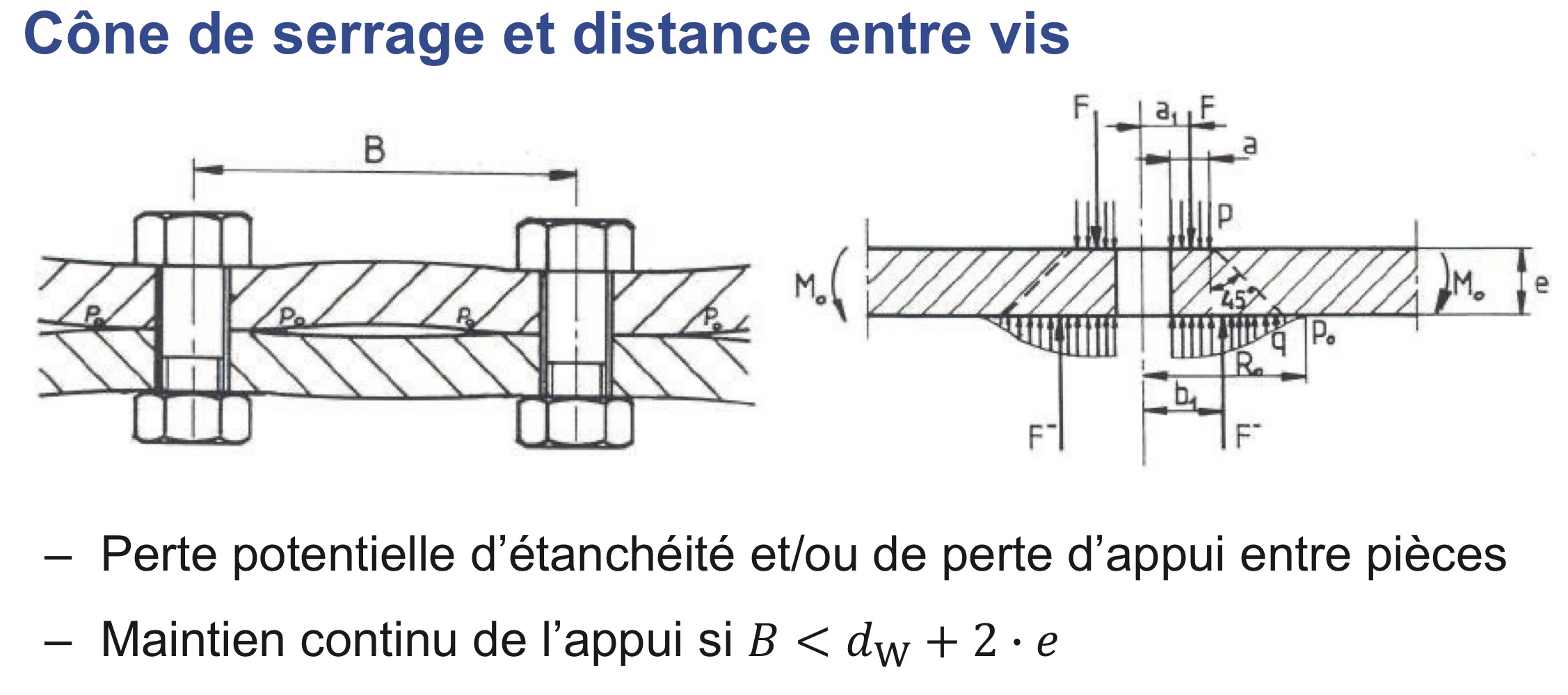
- Determining the length : We fixed the maximum length of a clamp using the following formula :
 ME-202_Systèmes Mécaniques (S.Soubielle)
This formula gives us the theorical maximum length between 2 screws considering their cone of pressure. This gives us that the maximum length of the piece in order for it to be tightened to the rod is :
, considering the use of M5 screws, we obtain :
Inputs
| Quantity | Value |
|---|---|
| Width of the rod () [mm] | |
| Width of the clamp () [mm] | |
| Total width () [mm] | |
| Head of the screw's diameter () [mm] |
Outputs
| 1 | 2 | 3 | |
|---|---|---|---|
| [mm] |
So we considered a maximum length of 56 mm.
- Determining the width : As the fin is fixed between 2 clamps, the width was fixed to be the half of the rod at the bottom (25 mm). Also, the presence of MPS in the engine bay forced the fin to be elevated of 10 mm so the clamp has a flat surface of 3 mm.
- Determining the height : Considering the fin clamped, we can use beam theory to estimate the deflexion of the fin under those forces (the height of the fin is then ).
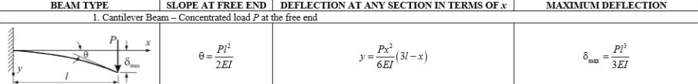 librarycivil.blogspot.com
We computed the force applied to the surface clamped and to do so :
a) We divide the force by the area ()
b) We multiply it by the length of the clamp and the maximal height of the fin (we surestimated to simplify)
Inputs
| Quantity | Value |
|---|---|
| Load () | |
| Area () | |
| Force by area () | |
| Height () | |
| Length () | |
| Inertia () | |
| Young's Modulus () | |
| Force () |
Outputs
| Quantity | Value |
|---|---|
| Delta () | |
| Beta () |
¶ Technical Drawings
Technical Drawing not made yet
¶ Possible Improvements
The main improvement to do is to reduce the mass.
¶ Technical Budget, Margins and Deviation
¶ Design Constraints
¶ Constraints for Production
The order of the assembly is the following :
- Pin 2 clamps together
- Glue the fin to the clamps
- Screw the clamps to the rods
- Mount the airframe panels
¶ Constraints for Operation
We must be careful about the alignment of the fin