¶ Introduction
¶ Purpose, Objective and Scope
This document is separated in to two sections, the test specification and the test procedure.
The test specification section defines the purpose of the test, the test approach, the item under test, test sequence, test facility, pass/fail criteria, required documentation, participants and test schedule.
The test report section gives directions for conducting a test activity in terms of description, resources, constraints and provides detailed step‐by‐step instructions for conducting test activities with the selected test facility and set‐up.
This document covers the preparation and the procedure for carrying out compression tests on a whole module of the Firehorn rocket, in order to determine the maximum load it can withstand.
In particular, it focuses on the buckling behavior of the module and its critical load. These tests are destructive.
It provides the guidelines to the person performing such tests.
It covers the testing protocol as well as the different points of analysis.
It does not cover the actual analysis of the results, neither the test report.
¶ Test Documentation
There are 3 main types of types of documents which relate to testing activities.
¶ AI&T
- High level overiew of testing activities
- Highlights dependancies in between types of tests
- Tracks the status of each type of test
- Document should be prepared as early as possible after PDR
¶ TSP
-
Test specification section explains:
- What part/assembly is being tested during each test.
- What characteristic is being tested.
- Brief description as to how the test is goind to be conducted.
- Explains the Pass/Fail criteria for each step.
- Explains when the test is due to happen and who will be involved in the test.
-
Document should be prepared after the baseline AI&T and ~1 month before the actual test.
-
Test procedure serves as a detailed plan for each individual test, it contains (among other things):
- A list of tools and instrument needed for the test.
- A description of the test location and condition.
- A step by step procedure of what needs to be done before, during and after the test.
-
Document should be prepared after the test specification and at least ~1 week before the actual test.
¶ TR
- The test report contains:
- The "as run procedure", meaning the procedure as planned ~1 week before the test with all of the comments and modiciations which were done the day of the test.
- The results of the test and all of the test data (or at least a link to the test data).
- If applicable, the analysis of the test data.
- The conclusion.
- The baseline document should be prepared the day of the test and the final version should be ready ~1 week after the test
¶ Definitions and Abbreviations
- ST : Structure
- FoS : Factor of Security
- ERT : EPFL Rocket Team
- ABR : Anti-Buckling Ring
- CFRP : Carbon Fiber Reinforced Polymer
- FEA : Finite Elements Analysis
- AV : Avionics
- PPE : Personal Protective Equipment
¶ Applicable and Reference Documents
- 2024_C_ST_INTERNAL-STRUCTURE_DDF
- 2024_C_ST_MODULE_FEA
- 2024_C_ST_NON_LINEAR_BUCKLING_MODULE_FEA
 2024_C_ST_BUCKLING-MODULE_TR
¶ Requirements to be verified
- 2024_C_SE_ST_INTERNAL-STRUCTURE_REQ_05
Axial compression
The internal structure shall withstand [15000]N of compression without failure.
- 2024_C_SE_ST_INTERNAL-STRUCTURE_REQ_06
Buckling
The internal structure shall withstand [15000]N of compression without loss of stability (buckling).
¶ Test Specification
¶ Open issue, Assumption and Constraint
For this test, the test parts at the ends of the module are simplified versions of the coupler with flat surfaces compatible with the press rather than the coupler interface. This does not change the resistance of the modules in compression since all the loads are taken up by the rods and the ABR.
¶ Test Description
Objectives:
This test aims to validate the resistance of the module in compression according to the requirement and to see up to what load it resists. The value of the critical force can then be compared with the simulations carried out previously and will allow the simulation model to be improved to approach the true value given by the test.
Furthermore, for the AV bay module one test will be done with an ABR and one without, to show how much the ABR strengthens the structure against buckling and to know if an ABR is necessary for this particular module.
Method:
After being assembled using a torque wrench to control the torque inside the screws, each module will be placed in a press. It will first be subjected to a 15[kN] compression force for a certain time to validate the requirement and see if there is creep, and then to an increasing compressive load until the module breaks.
Three modules will be tested. Two AV bay modules (one with an ABR, one without) and one pressurant bay module with two ABRs.
Environment:
This test must take place in a specialized laboratory, with high capacity presses and the necessary protective equipment to protect against the carbon shards that the breakage can cause.
Data and Scenarios:
The expected data is the load at which the module breaks. If possible, the use of a high-speed camera would help identifying the origin of the rupture.
Tools:
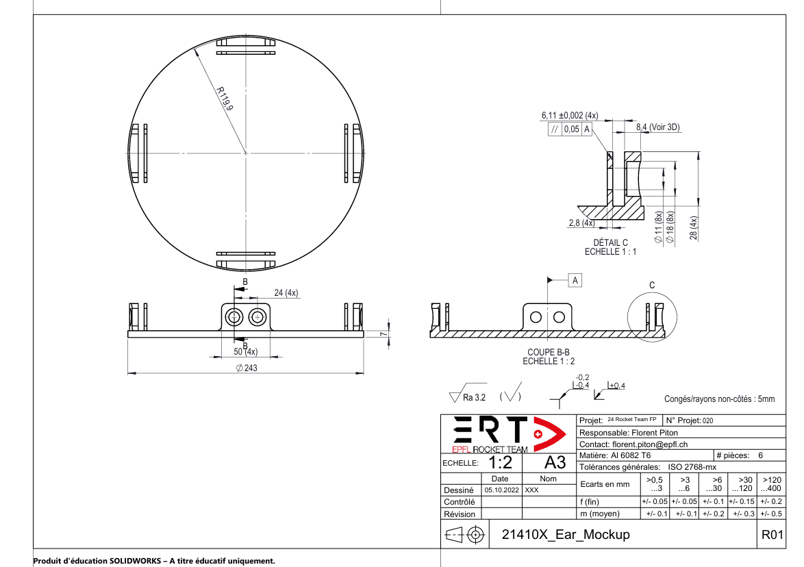
As part of the semester project "Composite Testing" carried out by Vianney Jacob and Florent Piton, buckling tests were conducted on assemblies. The test assemblies were made up of rods similar to those intended for flight, as well as the antibuckling rings. Regarding the couplers, they were replaced with simplified parts to reduce machining costs. These parts were made of Al6082 T6 to preserve the airware aluminum for the flight parts.
For each module:
- 2 simplified couplers
- 4 CFRP rods
- One or two ABR (could be none)
- 16 M10x18 screws
- 16 M10 nuts
- 4 M5x10 screws (for each ABR)
- 4 M5 nuts (for each ABR)
General tools:
- 1 Torque wrench
- 1 Press
- Sensors
- Lightning
- Cameras
- PPE
¶ Test Sequence
No constraints on the testing activities sequence were identified.
¶ Pass/Fail Criteria
Each module withstands a load of 15[kN]
No ear deformation
No ABR deformation
No cracks
No rod delamination
All screws are intact
No visible deformation after load removal
Rupture before the required force
Crack or delamination before 15 [kN]
Deformation of the ears of the ABR before 15 [kN]
One or more screws break before 15 [kN]
Delamination before 15 [kN]
¶ Test Organisation
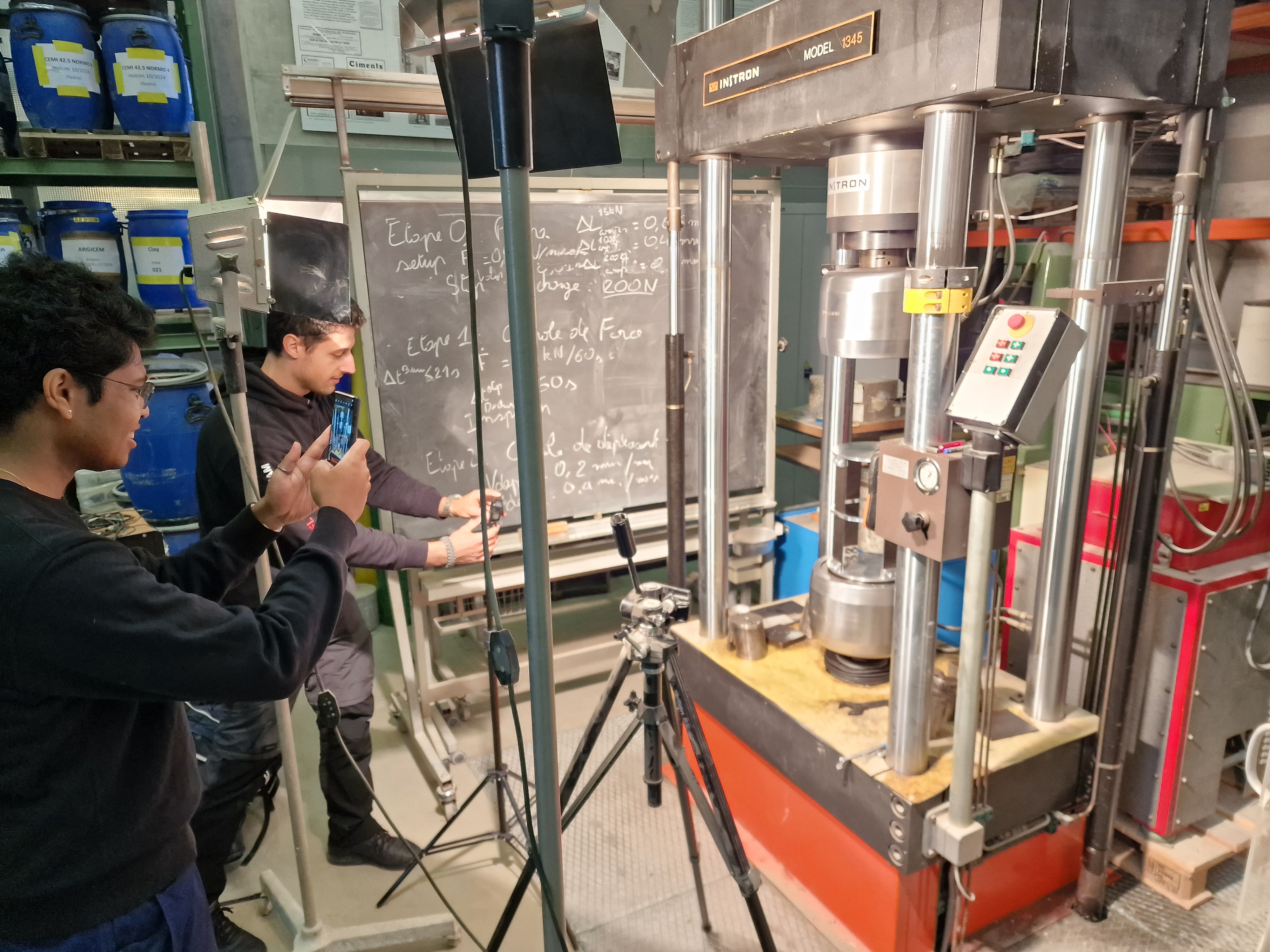
This test will be performed by the students in charge of the composite testing semester project, under the supervision of the LMC team.
It will take place on November 22, 2024.
Location: LMC
¶ Test Procedure
¶ Item Under Test
| Part Name | Number of parts | Specification |
|---|---|---|
| Avionics Bay | x2 | Only internal structure, adapted for the test |
| Pressurant Bay | x1 | Only internal structure, adapted for the test |
| Rod | x12 | x8 rods of length 350[mm] for AV bay, x4 for of length 700[mm] for pressurant bay |
| Ear Mockup | x6 | Test version of the coupler, with flat surfaces instead of coupler interface |
| Antibuckling Ring | x3 | - |
| Screw M10x18 10.9 | x48 | - |
| Nut M10 10.9 | x48 | - |
| Screw M5x20 10.9 | x12 | - |
| Nut M5 10.9 | x12 | - |
¶ Test Set-up
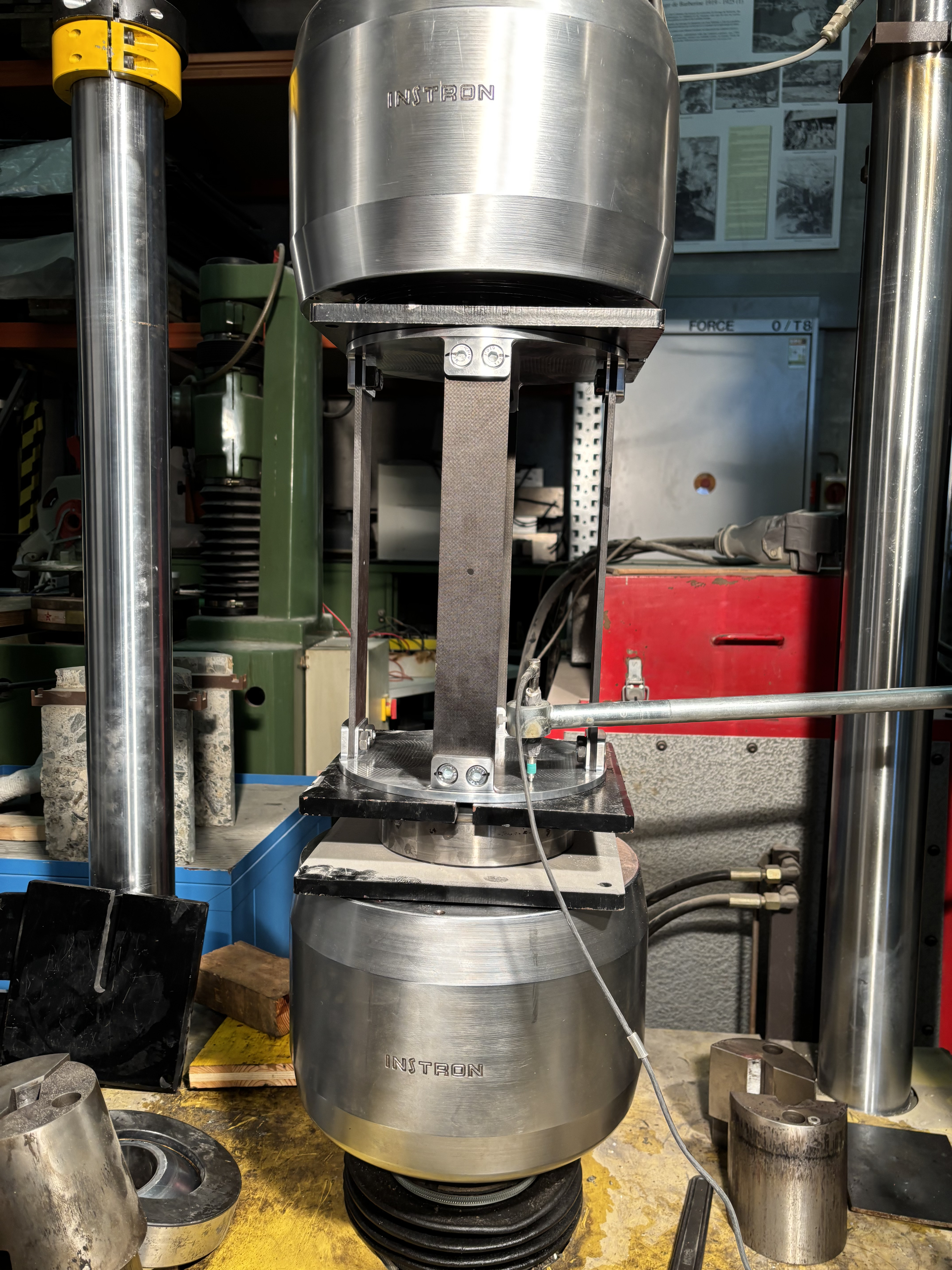
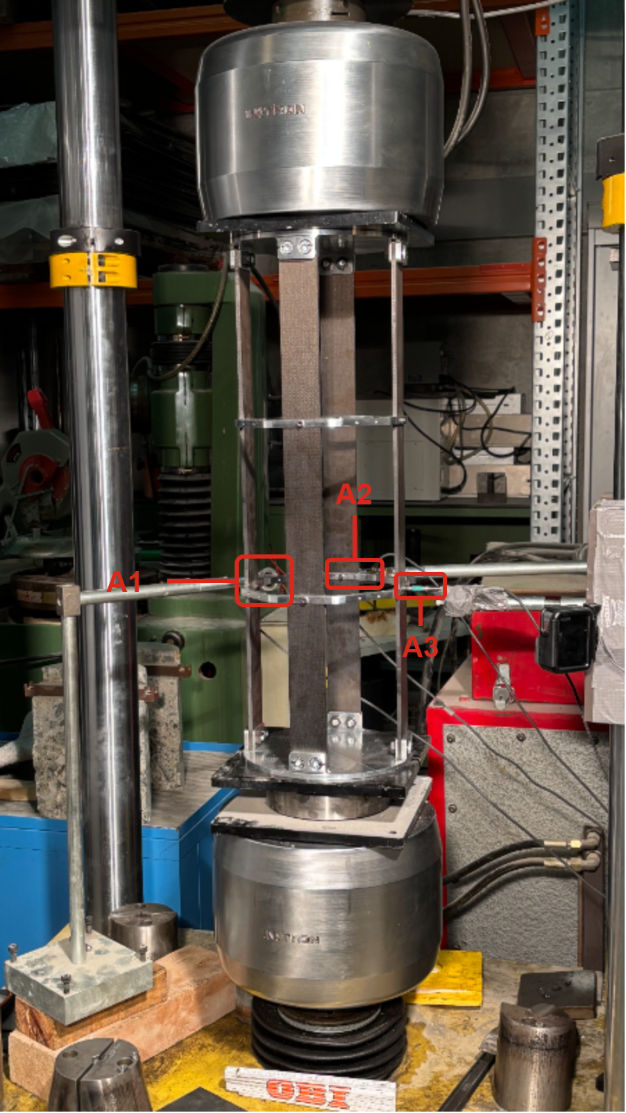
The setup in the press is the same for all modules and is composed as detailed here, from bottom to top:
- One steel plate
- A ball joint
- One steel plate
- One module
- One steel plate
A ball joint is used to make sure the module is perfectly aligned with the press and vertical. The plates must be larger than the module to ensure a good distribution of loads across the entire module.
Spotlights and tripods are used for the cameras.
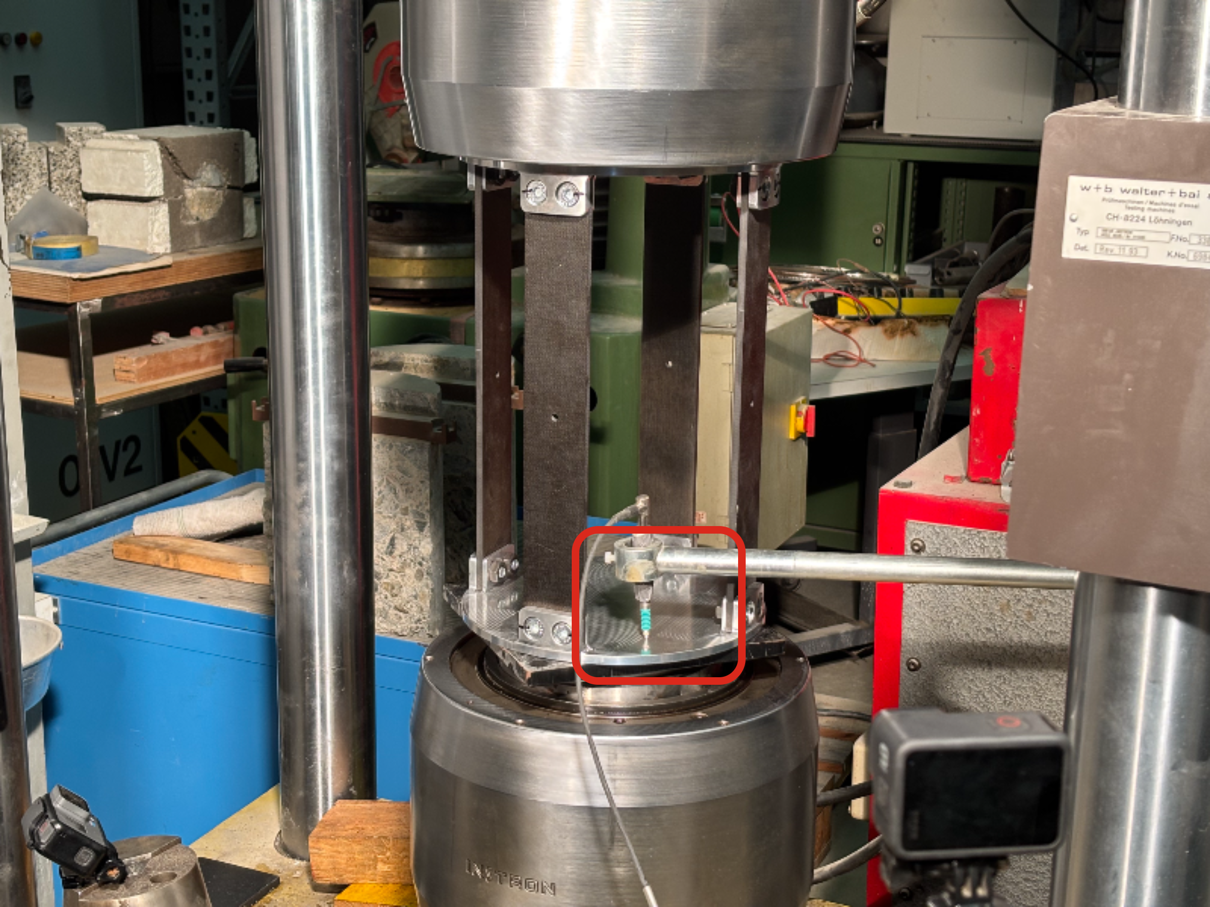
For this first module, a sensor was placed on the lower part to measure the displacement and compare it with that measured by the machine.
The rods in this module have holes in the center of each one. This is due to a production error. Normally, these holes should not be present. We are aware that this may weaken the rods and reduce their performance.
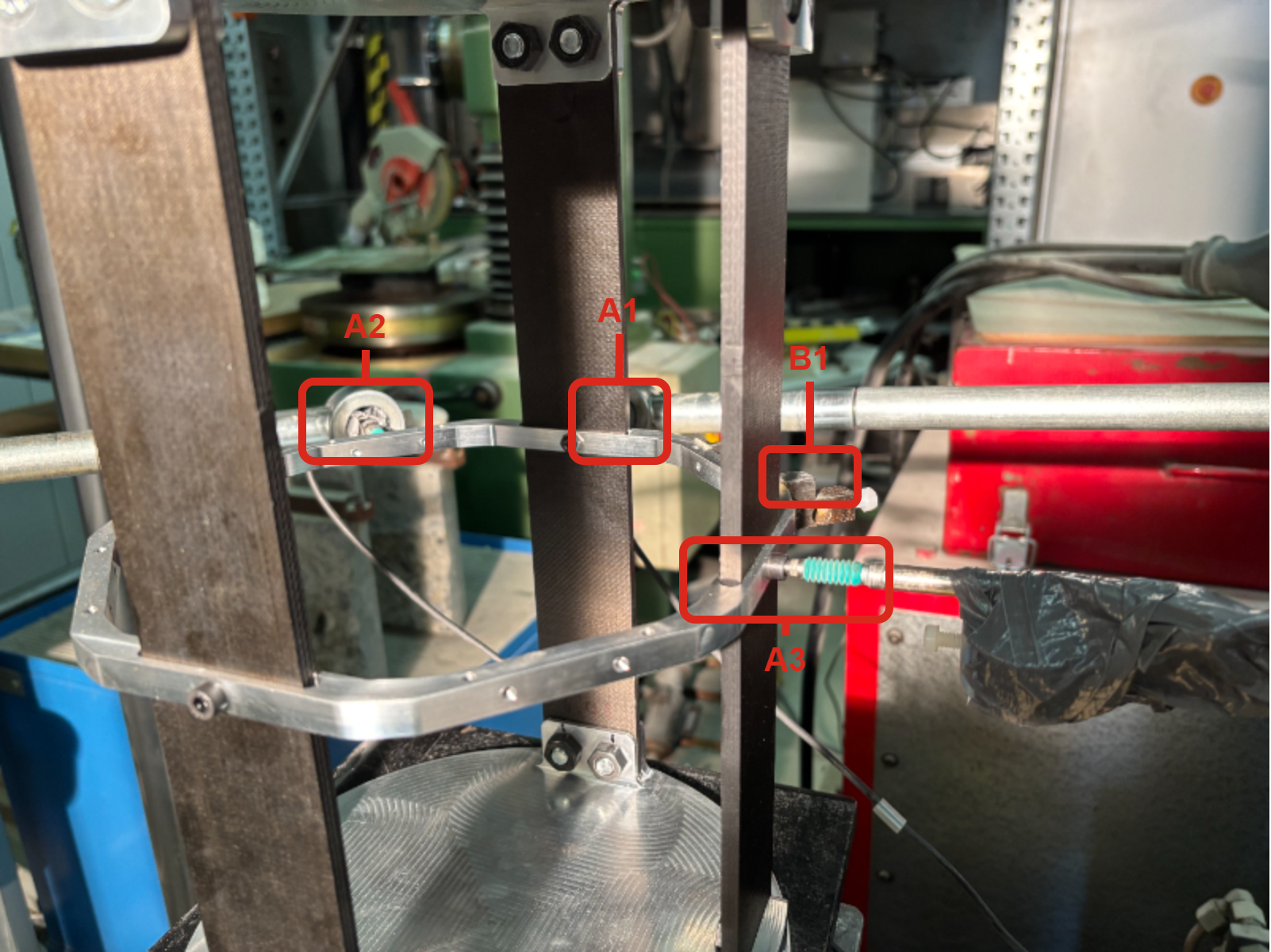
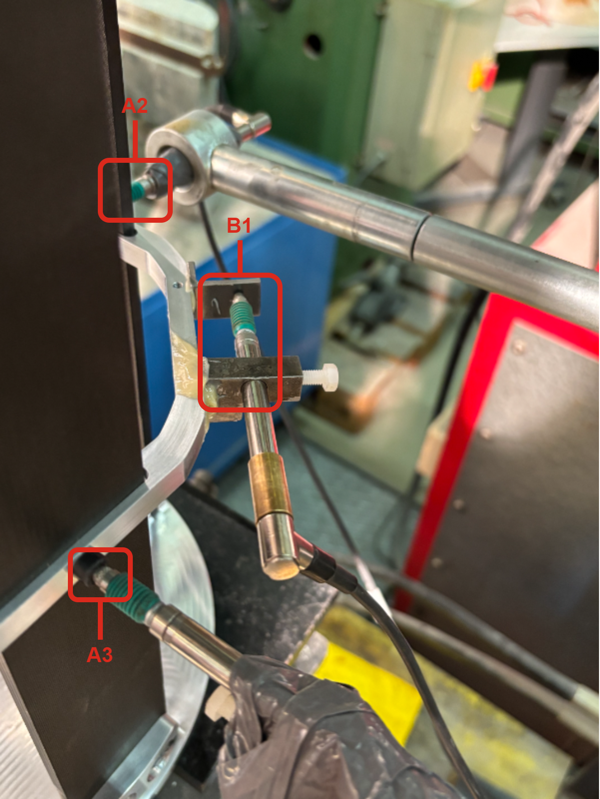
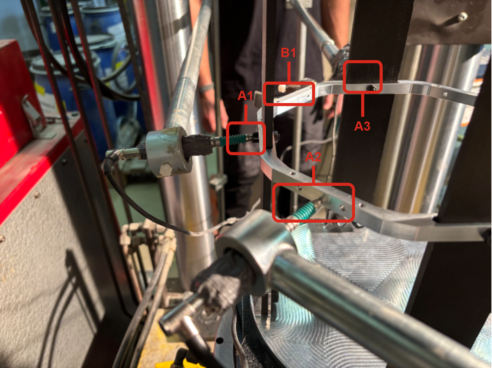
For this module, sensors were placed on the anti-buckling ring to measure its displacement values. Sensors A1 and A3 measure the displacement of the anti-buckling ring at the rods, and are located respectively on the rear and right rod. Sensor A3 is positioned radially on the left rear quarter. Sensor B1 is positioned parallel to the ABR on the right rear quarter.
 |
 |
 |
|---|
The sensors have been positioned in the same way as for the module with a single ABR
¶ Test Equipment Checklist
| Check | Quantity | Equipment |
|---|---|---|
| 8 | CFRP Rod 350[mm]x50[mm]x6.11[mm] | |
| 4 | CFRP Rod 700[mm]x50[mm]x6.11[mm] | |
| 6 | Test coupler | |
| 3 | ABR | |
| 48 | M10x18 screws | |
| 48 | M10 nuts | |
| 12 | M5x16 screws | |
| 12 | M5 nuts | |
| 1 | Torque Wrench | |
| 1 | Socket box | |
| 1 | 7[mm] key | |
| 1 | Camera | |
| 1 | Tripod | |
| 1 | High-speed camera (if found) |
¶ Test Instrumentation Description
All sensors are provided by the LMC.
Many displacement sensors will be placed vertically and horizontally on each module to measure the displacement of the module during the test
Other displacement sensors will be placed on the ABR to measure if the ABR is in tension or compression when the module is under compression.
¶ Test Location and Conditions
The test takes place in the LMC laboratory at EPFL under normal conditions.
¶ Test Safety
| Safety Concern | Probability | Impact | Severity | Mitigation | Post-Mitigation Probability | Post-Mitigation Impact | Post-Mitigation Severity |
|---|---|---|---|---|---|---|---|
| Rupture of the rods | High | High (carbon fiber splinters) | High | Put protective panels around the press, wear appropriate PPE | High | Low | Low |
| Rupture of the ABR | High | Medium | Medium | Wear appropriate PPE | High | Low | Low |
| Rupture of one or more screws | High | Medium | Medium | Wear appropriate PPE | High | Low | Low |
In any case, it is important to keep your distance from the press during the test for safety reasons.
¶ Tasks and Step-by-Step Procedure
¶ Before Test
| Done ? | Task |
|---|---|
| Do a meeting with LMC to prepare for the tests | |
| Send to LMC the technical drawings of the tested parts | |
| Assemble the different modules | |
| Make sure the screws for the ears are tighten with a torque of 70[Nm] | |
| Make sure the screws for the ABRs are tighten with a torque of 10[Nm] | |
| Prepare the necessary tools | |
| Prepare the camera |
¶ During Test
| Done ? | Task |
|---|---|
| Setup correctly the press with the help of LMC's team | |
| Place one module in the press (using the ball joints to ensure that the module is vertical) | |
| Attach all sensors to the module and connect them properly to the instrument that records the data | |
| Install all protective equipment | |
| Install the camera | |
| Compress the module to a load of 15[kN] with force control | |
| Keep this load for one minute | |
| Go back to a force of 0[kN] and inspect for any damage | |
| Compress the module until rupture with displacement control |
¶ After Test
| Done ? | Task |
|---|---|
| Report any crack, any damage on each module | |
| Analyze the videos to see where failure occured | |
| Analyze the results from the sensors |