¶ Goal(s) of the study
This FEA simulation was performed as a conclusion to the Bachelor Project on Composite Anti Buckling Rings, as an opening for a more optimized ABR design, attempting to find a composite anti buckling ring capable of competing with the aluminum ones.
We use linear buckling in order to find the load factors for different buckling modes, and then use the factors to compare to different ABRs.
The new design looks like this:
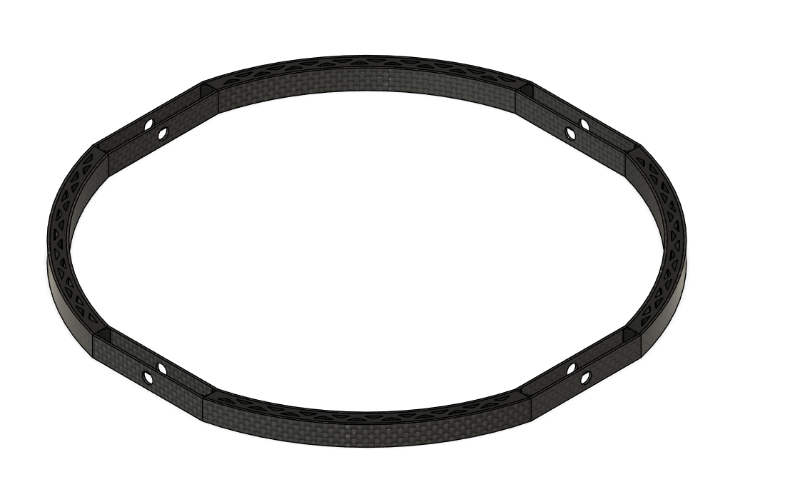
The idea behind is to optimize the use of the carbon, assuming the fibers directly connected to the spacers are the most important ones, and reduce the weight of the spacers by leaving empty space (inspire by a honeycomb).
This report is essentially the same as this one: Composite Eigenvalue Buckling Analysis but with a new ABR model.
¶ Parts Involved
¶ Geometry
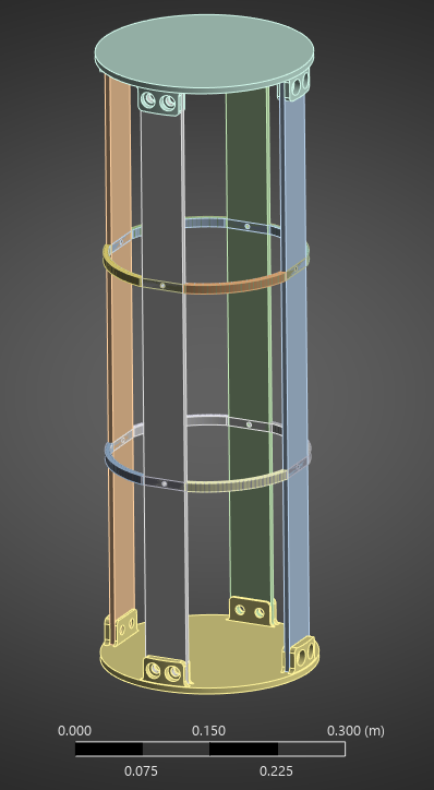
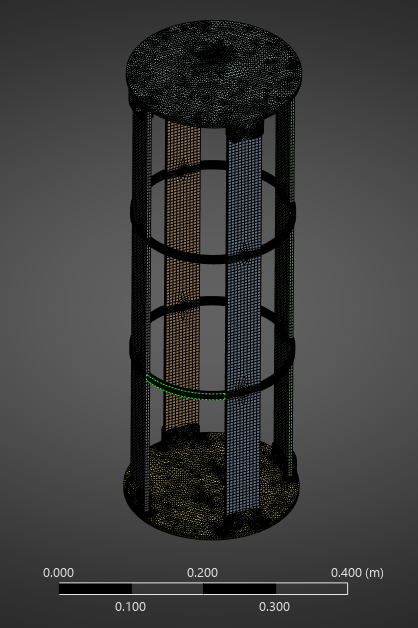
The Geometry used is the Pressurant Bay assembly, composed of two couplers,4 rods, and 2 ABRs.
2 Couplers
2 ABRs
4 CRFP Rods
¶ Function
This module ensures the structural integrity of the rocket and supports all loads applied to it: motor compression loads, parachute tension loads, and - specific to this module - the COPV's weight.
¶ Material
The Couplers are made of aluminum 2050-T6.
The rods are made of CFRP whose layup is described in 2024_C_ST_CFRP-PLATE_MAP.
The ABRs are made of CFRP.
¶ Load case
The module must withstand all the loads applied to the rocket. This analysis focuses on lift off, when the rocket is subjected to compressive forces and must resist buckling.
¶ Parts List
General Module
¶ Finite Element Analysis
¶ Software
- ANSYS Mechanical
¶ Type of simulation
- Linear buckling
¶ Inputs
SI units m-kg-N-Nm-Pa-m^4-J
The couplers doesn't have the coupler interface, only a flat surface instead.
The screws and nuts are removed to simplify the contacts.
The MPS mounting holes of the ABRs were removed to simplify (already complicated) mesh.
Otherwise, the geometries are kept as is.
¶ Aluminum alloy 2050 T6
| Density (g/cm^3) | Young's Modulus (GPa) | Poisson's ratio |
|---|---|---|
| 2.7 | 76.5 | 0.33 |
¶ CFRP
The CFRP properties have been defined using ACP.
The properties for the UD and woven plies are:
| Material | Density (g/cm^3) |
|---|---|
| UD | 1.47 |
| Woven | 1.49 |
| | Elastic (Engineering constants) |||||||||
| Material | E1 | E2 | E3 | Nu12 | Nu13 | Nu23 | G12 | G13 | G23 |
|---|---|---|---|---|---|---|---|---|
| UD | 137000 | 10500 | 10500 | 0.3 | 0.3 | 0.51 | 5200 | 5200 | 3476.82 |
| Woven | 49000 | 49000 | 10000 | 0.05 | 0.35 | 0.35 | 5000 | 4500 | 4500 |
In ACP, the layup from 2024_C_ST_CFRP-PLATE_MAP was defined, which gave the following properties for the CFRP rods using an orthotropic model:
| Density (g/cm^3) | E1 | E2 | E3 | Nu12 | Nu13 | Nu23 | G12 | G13 | G23 |
|---|---|---|---|---|---|---|---|---|
| 1.5 | 88074 | 17739 | 10000 | 0.3 | 0.3 | 0.3 | 3500 | 4081.6 | 3192.2 |
¶ Carbon Fiber ABRs
¶ PETCF
The DLL's PETCF's Datasheet provided the Young's Modulus as well as the density, from there, we found the Poisson Ratio based on research of other similar 3D printed materials (PETG) and we found the Shear Modulus using the formula to find G based on E and the Poisson Ratio.
|||||||||||
| | Elastic (Engineering constants) |||||||||
| Material | E1 | E2 | E3 | Nu12 | Nu13 | Nu23 | G12 | G13 | G23 | Density |
|---|---|---|---|---|---|---|---|---|---|
| UD | 6030 | 6030 | 3200 | 0.38 | 0.28 | 0.28 | 2185.5 | 2355.5 | 2355.5 |1.3g/cm^3|
¶ Carbon Fiber
The properties for the UD plies are:
|||||||||||
| | Elastic (Engineering constants) |||||||||
| Material | E1 | E2 | E3 | Nu12 | Nu13 | Nu23 | G12 | G13 | G23 | Density |
|---|---|---|---|---|---|---|---|---|---|
| UD | 130000 | 8600 | 8600 | 0.27 | 0.4 | 0.27 | 4700 | 3100 | 4700 |1.55g/cm^3|
The E1 and density were taken from the UD prepreg's datasheet - the rest was kept as standard values from Ansys' material libraries (which were compared to standard UD CRFP).
The ACP module was then used to set up the lay ups, so the values of the entire module are calculated by Ansys.
This is a linear buckling analysis, so it is stationary.
The top of the module is fixed, as it would be attached to the rest of the launch vehicle. The other end has a 15kN force applied to it, and the X and Z displacements are fixed to simplify the simulation.
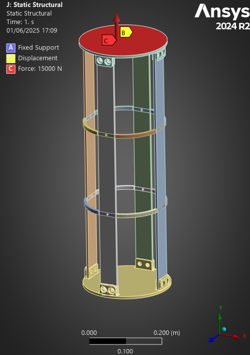
|:--- :---
:---
| Real case | Model |
| Attached to the top module | Fixed |
|Forced Upwards by the Motor | Horizontal displacements fixed + force |
The 0º Fibers were defined as shown:
The lay up used for the analyses was:
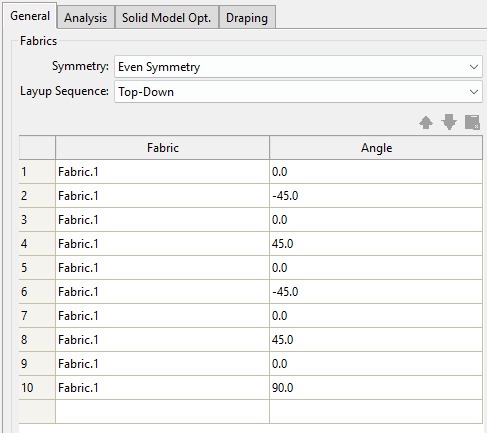
This layup was chosen to be a symmetric, balanced layup, to couple the least amount of "contraintes" possible.
A static structural simulation is performed followed by an eigenvalue buckling analysis. No nonlinearities are introduced. "Large Deformations" are turned on.
The eigenvalue buckling analysis uses the static structural solution as part of its set up.
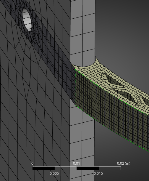
¶ Mesh
Element Type:
- 3D
- Mostly automatic, as hex dominant didn't work (surface to volume ratio too big)
Element order:
- Quadratic
No Mesh Refinements
The mesh being massive (requiring over 150Gb of RAM, where we used the PC's SSD as Virtual Memory, leading to simulations lasting upwards of 8 hours), and this analysis being completed at the end of the project - no mesh independency test was completed. This is only true for the last iteration of the mesh, where there were fewer than 1M elements - originally, there were 8M.
We used the same mesh settings for the couplers/rods as in previous simulations, but the ABRs have a 1mm mesh due to their geometry. This isn't sufficient, but it is, for now, better than nothing.
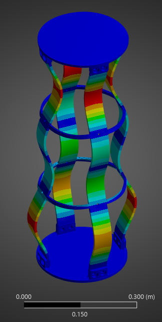
¶ Outputs
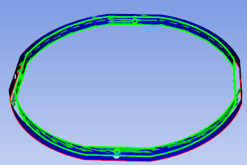
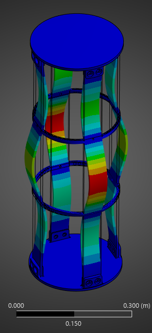
All Load Multipliers:
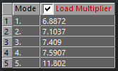
Mode 1:
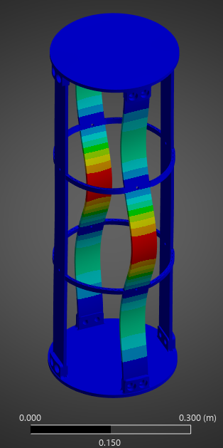
Mode 2:
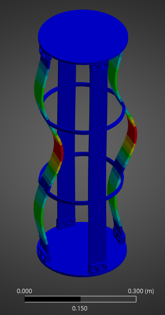
Mode 3:
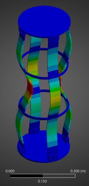
Mode 4:
Mode 5:
¶ Comparison
| ABR | Mass (g) | Carbon Mass (g) | Min Load Factor | Mass/LF Ratio | Carbon Mass/LF Ratio |
|---|---|---|---|---|---|
| H ABR | 213 | 178 | 7.12 | 29.9 | 25 |
| S ABR | 131.6 | 77.6 | 5.16 | 25.7 | 15.04 |
| New ABR | 124.64 | 94 | 6.89 | 18.09 | 13.65 |
| Aluminum ABR | 152g | N/A | 7.52 | 20.21 | N/A |
At an 18.09 Mass/LF Ratio, the New ABR outperforms every single ABR - at 13.65 Carbon Mass/LF Ratio, it also outperforms all the composite ABRs in carbon utilization.
¶ Interpretation
¶ Simulation validity
These results are somewhat validated thanks to coherent results and mode shapes, however the lack of mesh independency test is problematic.
This simulation should be followed up by a non linear buckling analysis.
¶ Conclusions
First of all, for all of these analyses, the Composite Failure tool indicated we were far from any possible composite failure. The maximum inverse reserve factor, (in which Tsai-Wu, Maximum Strain and Maximum Stress Criterions were taken into account) was 0.16.
Second of all, these results are highly satisfactory. As the concluding design of the Bachelor's Project, done in a final attempt to design a composite ABR that could perform - at the very least - similarly to the Aluminum ABRs, obtaining a simulation where the composite ABR performs better (in mass to load ratio) is very positive. A 10% improvement on the M/LF Ratio is, altogether, quite good! A 6.8 Load Factor is already "overkill" for anti buckling, so being able to reduce the weight by 20% - 25 grams - across multiple ABRs could be impactful at the launch vehicle scale.