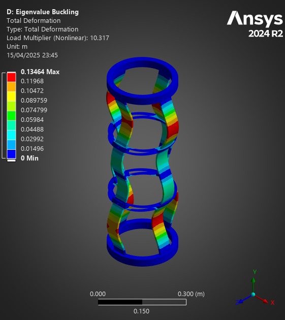
¶ Goal(s) of the study
These FEA simulations were performed in order to compare the performance of different Anti Buckling Rings in stopping buckling during the launch vehicle's compression loads. Specifically, we compare the original Aluminum ABRs and two ideas for Composite ABRs.
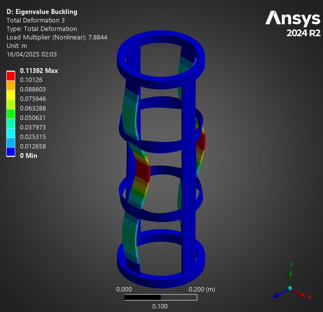
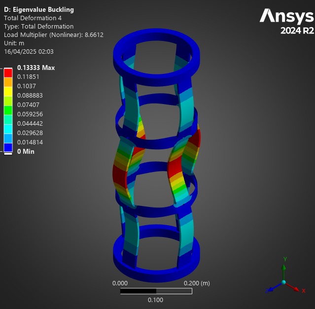
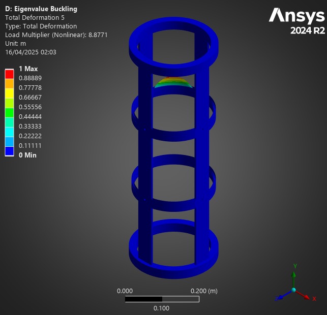
Linear Buckling allows us to compare different modes of buckling, and more importantly their load factor. We can then use the load factor to compare the performance of ABRs.
¶ Parts Involved
¶ Geometry
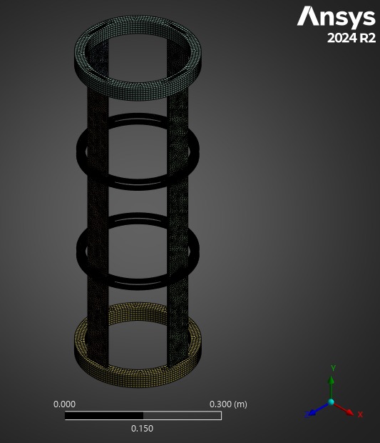
The Geometry used is the Pressurant Bay assembly, composed of two couplers,4 rods, and 2 ABRs.
2 Couplers
2 ABRs
4 CRFP Rods
¶ Function
This module ensures the structural integrity of the rocket and supports all loads applied to it: motor compression loads, parachute tension loads, and - specific to this module - the COPV's weight.
¶ Material
The Couplers are made of aluminum 2050-T6.
The rods are made of CFRP whose layup is described in 2024_C_ST_CFRP-PLATE_MAP.
The ABRs are made of CFRP.
¶ Load case
The module must withstand all the loads applied to the rocket. This analysis focuses on lift off, when the rocket is subjected to compressive forces and must resist buckling.
¶ Parts List
General Module
ABRs (one set/simulation)
¶ Finite Element Analysis
¶ Software
- ANSYS Mechanical
¶ Type of simulation
- Linear buckling
¶ Inputs
SI units m-kg-N-Nm-Pa-m^4-J
The couplers were simplified as a solid cylinder, as they are not the point of interest of this analysis. The rod <> coupler interface was simplified as "bonded." All nuts and screws were removed.
2 Cases were studied, one with Composite "H" ABRs, and one with Composite "S" ABRs. The results will be shown separately in the Outputs section.
The aluminum ABRs were studied in this FEA Report: 2024_C_ST_MODULE_FEA
¶ Aluminum alloy 2050 T6
| Density (g/cm^3) | Young's Modulus (GPa) | Poisson's ratio |
|---|---|---|
| 2.7 | 76.5 | 0.33 |
¶ CFRP
The CFRP properties have been defined using ACP.
The properties for the UD and woven plies are:
| Material | Density (g/cm^3) |
|---|---|
| UD | 1.47 |
| Woven | 1.49 |
| | Elastic (Engineering constants) |||||||||
| Material | E1 | E2 | E3 | Nu12 | Nu13 | Nu23 | G12 | G13 | G23 |
|---|---|---|---|---|---|---|---|---|
| UD | 137000 | 10500 | 10500 | 0.3 | 0.3 | 0.51 | 5200 | 5200 | 3476.82 |
| Woven | 49000 | 49000 | 10000 | 0.05 | 0.35 | 0.35 | 5000 | 4500 | 4500 |
In ACP, the layup from 2024_C_ST_CFRP-PLATE_MAP was defined, which gave the following properties for the CFRP rods using an orthotropic model:
| Density (g/cm^3) | E1 | E2 | E3 | Nu12 | Nu13 | Nu23 | G12 | G13 | G23 |
|---|---|---|---|---|---|---|---|---|
| 1.5 | 88074 | 17739 | 10000 | 0.3 | 0.3 | 0.3 | 3500 | 4081.6 | 3192.2 |
¶ Carbon Fiber ABRs
¶ PETCF
The DLL's PETCF's Datasheet provided the Young's Modulus as well as the density, from there, we found the Poisson Ratio based on research of other similar 3D printed materials (PETG) and we found the Shear Modulus using the formula to find G based on E and the Poisson Ratio.
|||||||||||
| | Elastic (Engineering constants) |||||||||
| Material | E1 | E2 | E3 | Nu12 | Nu13 | Nu23 | G12 | G13 | G23 | Density |
|---|---|---|---|---|---|---|---|---|---|
| UD | 6030 | 6030 | 3200 | 0.38 | 0.28 | 0.28 | 2185.5 | 2355.5 | 2355.5 |1.3g/cm^3|
¶ Carbon Fiber
The properties for the UD plies are:
|||||||||||
| | Elastic (Engineering constants) |||||||||
| Material | E1 | E2 | E3 | Nu12 | Nu13 | Nu23 | G12 | G13 | G23 | Density |
|---|---|---|---|---|---|---|---|---|---|
| UD | 130000 | 8600 | 8600 | 0.27 | 0.4 | 0.27 | 4700 | 3100 | 4700 |1.55g/cm^3|
The E1 and density were taken from the UD prepreg's datasheet - the rest was kept as standard values from Ansys' material libraries (which were compared to standard UD CRFP).
The ACP module was then used to set up the lay ups, so the values of the entire module are calculated by Ansys.
This is a linear buckling analysis, so it is stationary.
The top of the module is fixed, as it would be attached to the rest of the launch vehicle. The other end has a 15kN force applied to it, and the X and Z displacements are fixed to simplify the simulation.
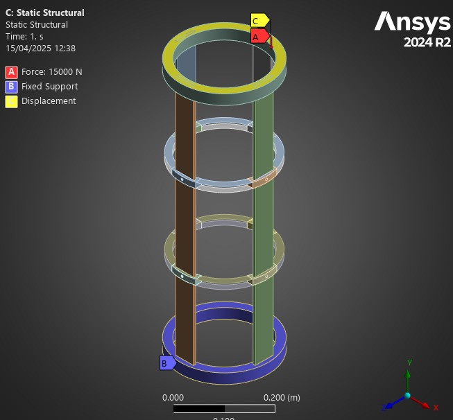
|:--- :---
:---
| Real case | Model |
| Attached to the top module | Fixed |
|Forced Upwards by the Motor | Horizontal displacements fixed + force |
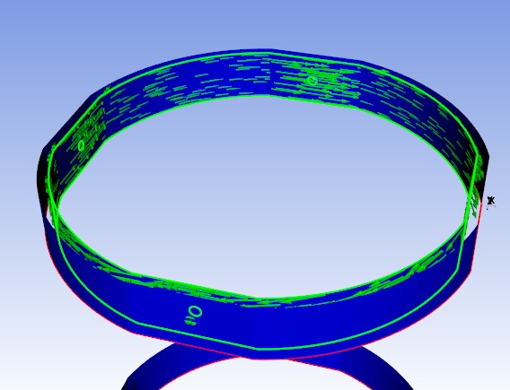
The 0º Fibers were defined as shown:
The lay up used for the analyses was:
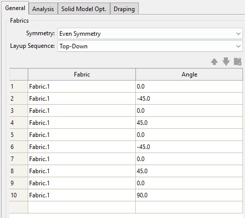
This layup was chosen to be a symmetric, balanced layup, to couple the least amount of "contraintes" possible.
For every simulation, a full 0º degree layup was attempted to serve as a comparison to the normal layup - the results are not shown in this report as the modes tended to have particularily bizarre behavior, although the load factors were <10% away from our previously defined layup.
For a more in depth tutorial of ACP Pre Set Up, the Engine Bay Dynamical Analysis: 2025_C_ST_EBAY_DYNFEA includes a more in depth "tutorial" of how to set up ACP, applied to one of these ABRs.
A static structural simulation is performed followed by an eigenvalue buckling analysis. No nonlinearities are introduced. "Large Deformations" are turned on.
The eigenvalue buckling analysis uses the static structural solution as part of its set up.
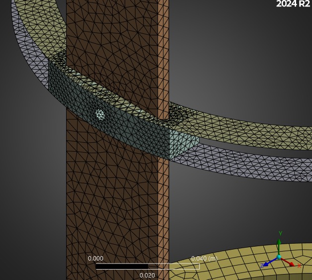
¶ Mesh
Element Type:
- 3D
- Hex Dominant where possible, otherwise Automatic
Element order:
- Quadratic
No Mesh Refinements
One independency test was used for both the HABRs and SABRs.
The sizes read "10-6" meaning 10mm for the rods and couplers, who are not the main subject of this study, and 6mm for the ABRs.
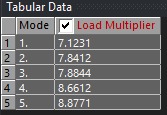
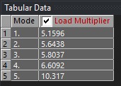
The first buckling loadfactor is used for the mesh independency test.
HABRs:
|:---:---:---:---:---
|Size|10-6|7-4.2|5-3|
First buckling eigenmode|7.03|7.10|7.12|
Deltas [%]|/|+0.98|+0.28|
SABRs:
|:---:---:---:---:---
|Size|10-6|7-4.2|5-3|
First buckling eigenmode| 5.168|5.163|5.159|
Deltas [%]|/|+0.1|+0.07|
Computationally, decreasing further in size would not have been feasible for this project, so we settled on the 5-3 size: 5mm on the couplers and rods, 3mm on the ABRs.
¶ Outputs
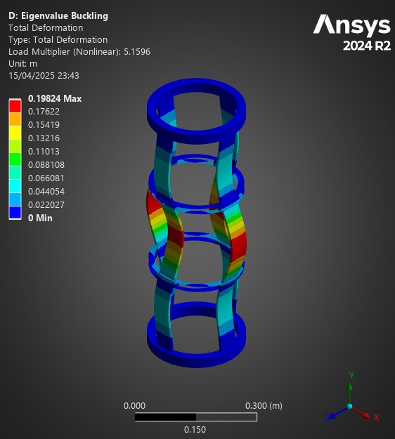
¶ Comparison
First of all, for all of these analyses, the Composite Failure tool indicated we were far from any possible composite failure. The maximum inverse reserve factor, (in which Tsai-Wu and Maximum Strain Criterions were taken into account) was 0.03.
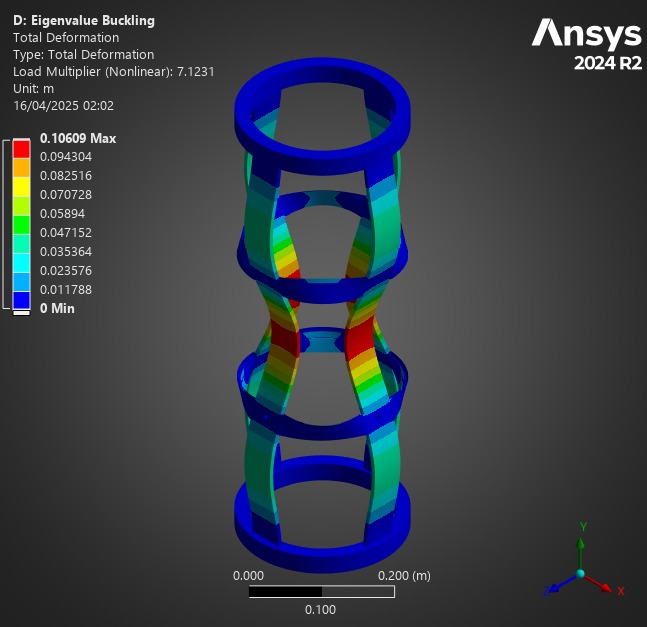
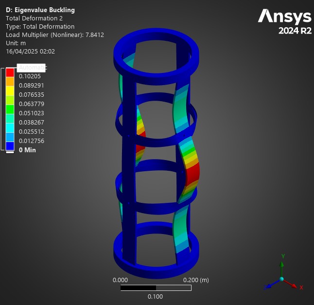
At a first glance, one may assume the H ABRs to be the best possible option, given their significant load factors, compared to other designs.
However, we are looking to optimise the load factor with respect to weight, so the most appropriate comparison is a mass/load factor ratio.
We also added a Composite Mass/Load Factor Ratio to see which models utilized the carbon fiber best, as the Composite ABRs also used "spacers" made of plastic, that add a significant amount of weight depending on the design.
| ABR | Mass (g) | Carbon Mass (g) | Min Load Factor | Mass/LF Ratio | Carbon Mass/LF Ratio |
|---|---|---|---|---|---|
| H ABR | 213 | 178 | 7.12 | 29.9 | 25 |
| S ABR | 131.6 | 77.6 | 5.16 | 25.7 | 15.04 |
| Aluminum ABR | 152g | N/A | 7.52 | 20.21 | N/A |
Given we want to maximize load factor, and minimize mass, we want the lowest ratio possible - thus, while the H ABRs have a better load factor, the S ABR is the best composite ring.
Unfortunately, neither of these ABRs beat the Aluminum ABRs in mass/load factor ratio, with the S ABR coming closest with 15.
This doesn't mean composite ABRs are useless - we simply believe they have to be optimized to minimize the weight of spacers (specifically for the H ABR) and look to optimize the ABR's geometry.
These examples serve more as guidelines for future development than fixed designs.
¶ Interpretation
¶ Simulation validity
These results are validated, as they provide similar results to past simulations done on the aluminum ABRs - which were validated in testing - and we observed satisfactory convergence in the mesh independency tests.
A non linear analysis would be a good follow up, but most likely more useful when a clearer ABR design has been found.
¶ Conculsions
The first design improvements we can think of are improving the spacer design - finding lighter weight materials, and limiting the amount of material used, through honey comb designs for example.
Next up, toying with the Carbon Fiber dimensions is probably interesting: does the ring diameter have an impact? Can we remove the center from the S rings, as those fibers are cut?
There is definitely space for improvement in these designs. The real question however, is: is the time taken to find an optimal solution worth it? I believe the difference in weight we can obtain by optimizing these designs relative to the time it would take to reach this optimization is not a valuable allocation of human ressources at the Rocket Team.