¶ Introduction
This document presents the design and the engineering process behind the conception of the separation mechanism - and its parts - a critical subsystem responsible for the safe and reliable decoupling of the rocket stages during flight. The document covers both the assembly level, detailing how all components interact to achieve separation, and the part level, providing specifications for individual components such as the pyrocutters, structural elements, and alignment features.
The goal was to build upon Nordend's (ERT's last rocket) separation mechanism, and improve it.
The separation mechanism was designed to :
- Ensure precise detachment of stages without affecting the trajectory.
- Withstand loads during launch and flight while maintaining reliability under varying conditions.
- Minimize mass and complexity while adhering to safety standards.
.drawio.png)
The document focuses on the Separation Mechanism Assembly, a critical subsystem responsible for the safe and reliable decoupling of the rocket stages during flight. The document covers both the assembly level, detailing how all components interact to achieve separation, and the part level, providing specifications for individual components such as the pyrocutters, structural elements, and alignment features.
¶ Definitions and Abbreviations
- SepMech : Separation Mechanism
- CB : Clamp Band (SepMech part)
- AV : Avionics
- LV : Launch Vehicle
- REB : Recovery Bay
- AVB : Avionics Bay
- PLB : Payload Bay
- ERT : EPFL Rocket Team
- DDF : Design Definition File
¶ Applicable and Reference Documents
- 2024_C_ST_COUPLERS_DDF
- 2024_C_ST_SEPARATION_MECHANISM_DJF
- 2024_C_ST_PYRO-CUTTER_DDF
- SEPMECH MATLAB
- NORDEND SEPARATION MECHANISM
- Full Firehorn Requirements Tableset
¶ Requirements
- 2024_C_SE_ST_REQ_01
The Separation Mechanism shall allow the LV to separate and deploy a drogue parachute or a reefed parachute at apogee.
- 2024_C_SE_ST_REQ_02
The Separation Mechanism shall not interfere in any way with the deployment of the RE systems.
- 2024_C_SE_ST_REQ_03
The Separation Mechanism shall result in a free internal diameter larger than [200]mm.
- 2024_C_SE_ST_REQ_04
The Separation Mechanism shall deploy in less than [3]s.
- 2024_C_SE_ST_REQ_05
The assembly of the Separation Mechanism shall take less than [15]min.
- 2024_C_SE_ST_REQ_06
After it has been used, it shall cost less than [20]CHF to repair the Separation Mechanism.
- 2024_C_SE_ST_REQ_07
The Separation Mechanism shall withstand a bending moment of [3000]Nm around an axis perpendicular to the main LV axis.
- 2024_C_SE_ST_REQ_38
The FH I LV shall resist compression induced by a compression force of [10000]N instead of [15000]N.
¶ Functional overview and part breakdown
¶ Global interface overview
The chosen location of the SepMech necessitates structural interfaces between the SepMech itself, the Shockpler coupler (AVB side), and the SepMech coupler (REB side). All of these components play a critical role in ensuring the smooth and safe deployment of the recovery system during flight.
The only non-structural interface lies between the Avionics setup located in the AVB.
A fully detailed interface listing will be given during the parts descriptions.
¶ Functional description
- The separation sequence is triggered by the Avionics (AV) system immediately after detecting apogee. For Firehorn I, the first event corresponds to the separation of the LV into two parts at the Separation Mechanism (SepMec), located between the Recovery Bay (REB) and the Avionics Bay (AVB) as stated above.
- This separation allows the deployment of the parachute, initiating the recovery sequence. It must occur promptly after apogee to ensure the parachute deploys before the descent speed becomes too high, which could cast excessive structural loads upon the LV.
The chosen design, similar to Nordend's, relies on clamping force to fasten and unify the LV. This design has demonstrated reliability in many previous ERT rockets and was selected early in the Firehorn project for its robustness.
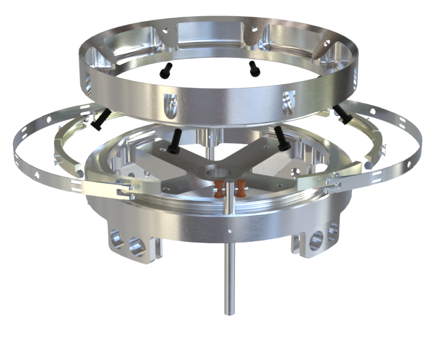
Therefore, the SepMech consists of three main components:
- Upper Ring: Upper ring half, REB-side, designed to be clamped to the Lower ring (opposite ring half).
- Lower Ring: Lower ring half, AVB-side, designed to be clamped to the Upper ring (opposite ring half).
- Clamp Band (CB): Spring steel band with metallic clamps attached to it. It is tightened via a screw to couple the Upper and Lower Rings, ensuring structural integrity under launch loads. During the first event, the CB is released and allows for stage separation.
¶ Design Specifications
| --- | --- |
| Height | 69.7 [mm] |
| External Diameter | 243[mm] |
| Internal Diameter | 195 [mm] |
| Weight | 1,41 [kg] (Aerocover excluded)|
| Material | Al 6082 T6 (Rings and clamps)|
| Material | Spring steel 1.4310 (CB) |
¶ Parts Description
This section provides an in-depth overview of the SepMech components.
For each part, a dedicated section comprises:
- Description
- Interfaces
- Analysis and simulations
- Main Specifications
- Technical drawing
.png)
¶ Upper Ring (SepMech coupler)
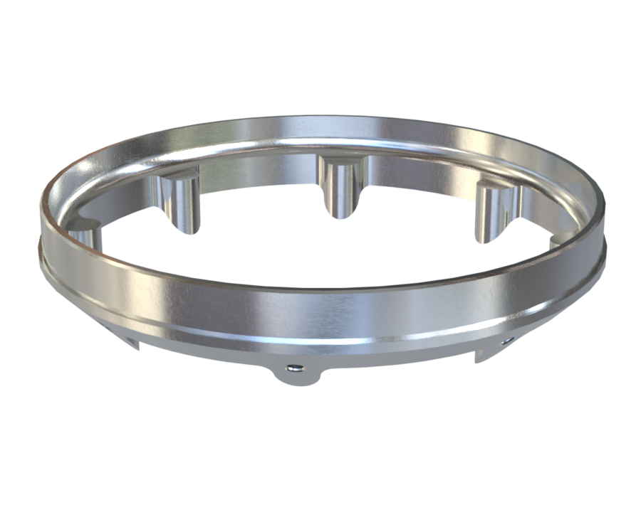
¶ Description
The Upper Ring is a structural half-ring directly integrated onto the SepMech coupler. The latter was designed to provide a rigid connection between the REB and the SepMech. In this document, only the ring part of the coupler will be described (all information about the coupler itself can be found in the Coupler DDF linked above). The outer side of the ring includes a groove for interfacing with the Clamp Band (CB) and maintaining alignment with the Lower Ring during flight.
¶ Main Specifications
| Specification | Value | Unit |
|---|---|---|
| Dimensions | 243 x 243 x 37 | [mm] |
| Mass | 856 | [g] |
| Material | Al 2050-T84 | - |
| Manufacturing cost | 240 | [CHF] |
¶ Interfaces
- With Recovery Bay: the SepMech coupler is bonded via epoxy to the REB tube for structural integrity.
- With Lower ring (Shockpler): in contact with the Lower Ring to form a unified ring, fastened by the Clamp Band.
- With the Clamp Band: in contact with the CB which fastens the two half-rings together.
¶ Analysis and Simulations
- The Upper Ring, and the entire Sepmech coupler, were designed and FEA simulated to handle compression forces linked to initial engine thrust, of 10 000 [N], as per 2024_C_SE_ST_REQ_38 (defined above).
- Bending resistance was achieved through FEA simulations, after force and stress analysis (using the SepMech Matlab script).
¶ Technical Drawings
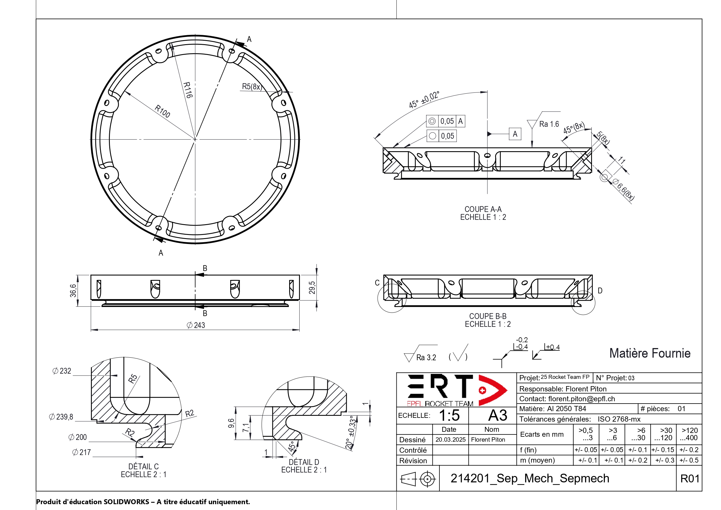
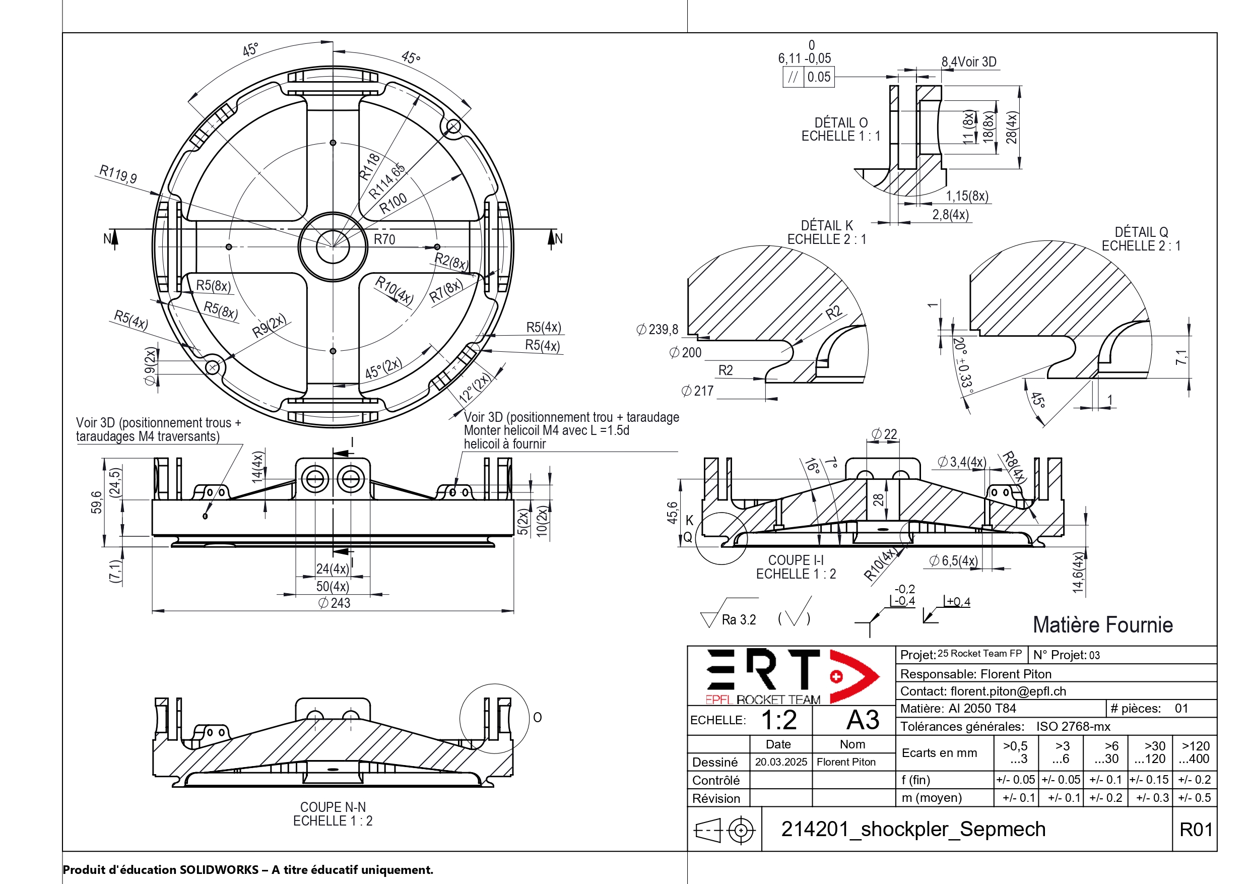
¶ Lower Ring (Shockpler coupler)
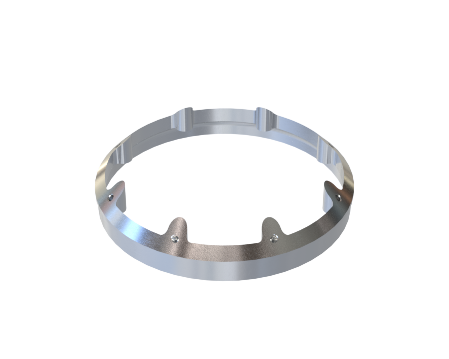
¶ Description
The Lower Ring is a structural half-ring directly integrated onto the Shokpler coupler. The latter was designed to provide a rigid connection between the AVB and the SepMech. In this document, only the ring part of the coupler will be described (all information about the coupler itself can be found in the Coupler DDF linked above). The outer side of the ring includes a groove for interfacing with the Clamp Band (CB) and maintaining alignment with the Upper Ring during flight.
¶ Main Specifications
| Specification | Value | Unit |
|---|---|---|
| Dimensions | 200 x 200 x 37.6 | [mm] |
| Mass | 353 | [g] |
| Material | Al 2050-T84 | - |
| Manufacturing Cost | 240 | [CHF] |
¶ Interfaces
- With Avionics Bay: the Shockpler coupler's bottom part is designed to be linked to the AVB via M10 and M4 screws.
- With Upper ring (Sepmech coupler): in contact with the Upper Ring to form a unified ring, fastened by the Clamp Band.
- With the Clamp Band: in contact with the CB which fastens the two half-rings together.
¶ Analysis and Simulations
- The Lower Ring, and the entire Shockpler coupler, were designed and FEA simulated to handle compression forces linked to intial engine thrust, of 10 000 [N], as per 2024_C_SE_ST_REQ_38 (defined above).
- Bending resistance was achieved through FEA simulations, after force and stress analysis (using the SepMech Matlab script).
All couplers are required to be able to resist to traction forces of than 130 000 [N] in order to withstand parachute deployment events. This includes the Shockpler coupler, however the Lower Ring itself is not required to respect this requirement.
Indeed, since the Lower Ring is part of the Separation Mechanism, its location is not structurally impacted by traction forces or used to withstand them.
This logic can also be applied to the Upper Ring, although the second shockplate is located at the upper end of the REB.
¶ Technical Drawings
¶ Pyrocutter
 !
!
¶ Foreword
To understand the Pyrocutter, its design and function, a few clarifications have to be made.
- The previous iteration of the SepMech (Nordend) was designed not with M3 screws as a fastening component, but rather with Dyneema.
- Indeed, a Dyneema cord was burned through by a pyrotechnic charge, releasing the CB (see pictures below for side-by-side comparison between the curent and previous iterations).
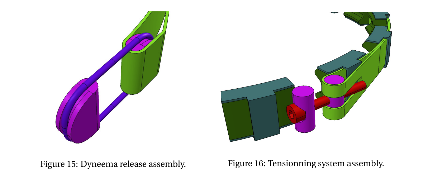
- This system presented multiple problems, including the delay between pyrotechnic charge triggering and clamp band unfastening, which resulted in the decision to change the mechanism from Dyneema to a more rigid and 'snap'-able, ie screws.
- The Pyrocutter is the component that destroys a portion of the screw, allowing the clamp band to be released in a swifter manner.
The Pyrocutter itself is a sensitive and intricate component, necessitating its own DDF file. A number of details will be only briefly mentioned in this document, as they are further developed in the dedicated Pyrocutter DDF.
¶ Description
The pyrocutter, as previously described, is a pyrotechnic device that severs the M3 screws in the Clamp Band to release the latter and initiate LV stage separation.
Two pyrocutters are positioned symmetrically on either side of the Clamp Band. They each sever an M3 screw upon simultaneously receiving an electrical signal from avionics triggered after apogee detection.
The pyrocutter is itself decomposed in multiple parts:
- A lower hollow cylindrical part (called 'powder chamber')
- A higher hollow cylindrical part (called 'body')
- A small electric igniter (called 'pyro charge')
- Black powder
- A small tungsten carbide projectile
- Epoxy glue
- A set screw
¶ Assembly
The 'powder chamber' features a tapped top part, as well as a small hole at its bottom, inside which the 'pyro charge' is fitted, and held in place with epoxy glue. It is then filled up to the top with 0.55 to 0.6 [g] of black powder.
A 6 to 7 [mm] long conical tungsten carbide projectile is fitted and epoxy glued on top of the 'powder chamber'. There is no risk of the projectile slipping inside the chamber, as it has a diameter of 5 [mm] while the chamber has an internal diameter of 4 [mm].
The 'body' is screwed onto this assembly. The body features two opposite holes on either side of it, to allow the M3 screws to pass through.
This is the full Pyrocutter assembly. It is then fitted to the Clamp band with an M3 screw passing through a Pyrocutter on each side of the LV, while both Pyrocutters are set in the Shockpler using set screws.
This is a base level explanation of the Pyrocutter assembly, to help understand its functionning. A more detailed description can be found on the Pyrocutter DDF.
¶ Reusability
One key requirement for this design is that it had to be somewhat cheat and reusable.
This was achieved; in normal operation, the 'body', 'powder chamber', and projectile can be recovered from a triggered pyrocutter and reused after cleaning (interior scrubbing, epoxy cleaning and dust removal for 'body' and 'powder chamber', and conical surface polishing for projectile).
¶ Main Specifications
| Specification | Value | Unit |
|---|---|---|
| Dimensions | 11 x 11 x 60 | [mm] |
| Mass | 5 | [g] |
| Material | Steel A36 | - |
| Manufacturing cost | 500 for 10 pieces | [CHF] |
These are the overall dimensions of the Pyrocutter, once it is fully assembled. For individual part dimensioning refer to the Pyrocutter DDF.
¶ Interfaces
- With Clamp Band: Positioned on either side to sever M3 screws upon activation.
- With AV: Electrically connected to AV for triggering, via a small electrically triggerable pyro charge.
- With Shockpler Coupler: the pyrocutter is inserted and pinned into the Shockpler.
¶ Analysis and Simulations
A series of analyses, FEA simulations and calculations were made in order to birth the Pyrocutter.
The easiest development method for the pyrocutter was determined to be testing. A series of more than 40 tests was established, to allow for optimal pyrocutter design.
Various parameters were analysed in an Excel file (see image below), including the dimensions of the pyrocutters, the shape of the projectiles (flat point, conical point, etc.), stresses applied by the Screw guide and nut, and screw torque.
The testing revealed that a body with an acceleration chamber of more than 20 mm was necessary to achieve sufficient velocity of the projectile. A 5 mm diameter, 6 mm long tungsten projectile required at least 0.45 g of black powder and a reservoir of 8 mm in diameter. For a 4 mm diameter projectile, more black powder and longer reservoirs were needed. Two different threading systems were tested to optimize the filling of the reservoir and the amount of powder.
The analysis section has been heavily abbreviated, and much more information regarding pyrocutter analysis can be found on the Pyrocutter DDF.
¶ Technical Drawings
_page-0001.jpg)
_page-0001.jpg)
¶ Clamp Band (CB)
.png)
¶ Description
The Clamp Band is the most intricate element of the separation mechanism, in terms of component number. The CB is a tensioned steel band that secures the Upper and Lower Rings together during flight.
A CB is made up by a number of different components:
- 1x spring steel band
- 4x clamps
- 10x M2.5 screws
- 2x M2.5 nuts
- 4x M2.5 washers
- 1x Screw Nut
- 1x Guide Nut
- 1x M3 screw
Their respective purpose in the mechanism will be further described below.
It must be noted that the list above corresponds to a single clamb band, fastening only 180 [deg] of the ring. The SepMech assembly therefore requires 2 CB to function. Each of these CB presents the list of components presented above. This choice was made to increase the number of M3 screws being destroyed (see below) from 1 to 2, in order to double stage separation probability.
A Clamp Band is assembled by linking the clamps to the steel band, then folding both extremities of the latter in order to fit a Guide Nut and a Screw Nut at each extremity, respectively.
The 2 Clamp Bands are fastened by tightening one M3 screw at either side of the Clamp Bands. The mechanism is released when the Pyrocutters detonate and destroy the M3 screws. Its flexibility allows for easy assembly and disassembly while maintaining a strong hold under operational loads.
¶ Part-specific precisions
-
Clamps:
The clamp design was made so that, when the CB is fully fastened, two surfaces (inside top and inside bottom) are precisely parallel to the Upper and Lower Ring interfaces. To ensure that the CB can be fully fastened without structural interference from the clamp, the latter was designed with a small central hollow space left out on the inside, compared to the Ring's shape. This allows for optimal fastening and force application on the inside top and bottom surfaces.
Each clamp is fastened to the band via two aligned 2.5 screws. This allows for adjustability and ease of operation when fastening the Clamp Bands onto the Rings. -
Band:
The band's chosen material is spring steel, to allow for fast and dynamic ejection of the clamp band after Pyrocutter detonation. Although 0,5 [mm] thick spring steel was strong enough to withstand calculated loads, 0,8 [mm] spring steel was chosen to maximise the spring effect and force.
The band is not uniformally wide, but rather adapted to maximise weight-saving while ensuring performance and ease of use. It is, however, uniformally thick. -
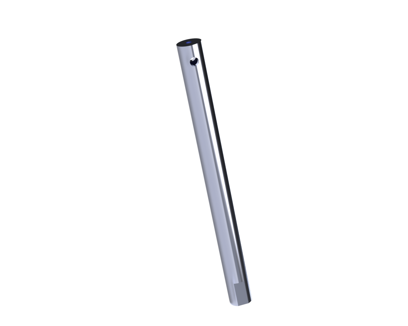
M3 screw:
8.8 class M3x30 screws were chosen to fasten both sides of the Clamp Bands as they are strong enough to resist traction loads caused by fastening, while remaining small enough to be destroyed by the Pyrocutters. One CB incorporates one screw, therefore one of these screws is present on each side of the SepMech once the latter is fully assembled.
The necessary torque to be applied to each of these of these screws has been calculated according to the SepMech MATLAB. The exact torque value is of 1.75 [Nm].
-
Guide and Screw Nuts:
These are designed to be respectively inserted into the loops on both ends of the Clamp Band. The Guide nut isn't tapped, while the Screw nut is; they, together with the M3 screws, are responsible for the fastening and tightening of the Clamp Band system. -
The M2.5 Screw-Nut-Washer system exists simply to create loops at each end of the Clamp Band, in order to fit the Guide and Screw nuts.
¶ Interfaces
- With Upper and Lower Rings: Wraps around and fastens them together.
- With Pyrocutters: both M3 screws pass through the Pyrocutters to be destroyed.
¶ Analysis and Simulations
Analysis of the Clamp Band
All parts in the Clamp Band were designed and FEA simulated to handle radial loads with safety factors of more than 2. The exact loads were calculated using the SepMech Matlab script.
However, some concerns were expressed about deformation of different SM components, namely the band and the clamps. This warrants the section below:
Analysis of the clamp deformation
¶ Design Constraints
¶ Constraints for Production
Precise machining of the Upper and Lower Rings, as well as the clamps to ensure a seamless fit.
¶ Constraints for Operation
The pyrocutter’s triggering must be thoroughly tested pre-flight to avoid misfire. Use of epoxy means that the pyrocutter has to be prepared in advance.
¶ Other Constraints
Transport must ensure no deformation of the rings or damage to the Clamp Band.
¶ Potential improvements
Two main improvements can be denoted when considering the separation mechanism:
-
The use of epoxy to secure certain parts of the pyrocutter means the latter has to be partially assembled in advance. In addition to epoxy simply being impractical and hard to get off when solidified, these operational constraints would justify the exploration of new ways to secure pyrocutter parts, without epoxy.
-
The band in the Clamp Band assembly has to be able to store a lot of energy so that it unfastens swiftly after pyrocutter triggering. Spring steel is perfectly suited to this role, however it does create some unnecessary difficulties when being assembled and fastened to the rings. Finding a way to utilise spring steel properties without suffering its consequences, or simply using a different material, could be considered.