¶ Goal(s) of the study
The goal of this study is to perform the first dynamical analysis on the Firehorn project, as part of the Bachelor's project on Anti Buckling Rings.
As an initial attempt at the dynamical analyses that was quickly discarded in favor of simulating the Engine Bay, some of the inputs/results were, unfortunately, not saved, so it is not a perfectly complete report.
We attempt to analyze the dynamical effects of the motor's thrust and the fin's lateral acceleration on the launch vehicles's pressurant bay, trying to determine if dynamical loads have any un-intended/un-foreseen impact on the launch vehicle, missed during static analyses.
The connection between these analyses and the Bachelor's Project on Anti Buckling Rings will be discussed in more depth in the Engine Bay Dynamical Analysis Report which you can find here: 2025_C_ST_EBAY_DYNFEA
Much of this simulation's set up is discussed in the Engine Bay Dynamical Anslysis, but will be included in both reports so as to avoid having to look through multiple documents for the same information. That being said, the document with the most explicit explanation of the set ups is the Engine Bay Report.
¶ Parts Involved
¶ Geometry
The Geometry used is the Pressurant Bay assembly, composed of the couplers, rods, and ABRs.
4 CRFP Rods
2 Aluminum ABRs
2 Couplers
¶ Function
The pressurant bay is the module containing the launch vehicle's COPV, attached to the bay via MPS. It ensures the rocket's structural integrity,and supports all loads applied to it - most notably the motor's compression loads, and parachute's extension loads, as well as lateral forces.
¶ Material
The different parts of the assembly are made of different materials
- Rods: these rods are made of CFRP, who's layup is described here: 2024_C_ST_CFRP-PLATE_MAP
- Couplers: the couplers are in Al6082-T6
- ABRs: the ABRs are in Al2050-T84
¶ Load case
The loads applied to the pressurany bay are, most notably:
- Motor Thrust: Compressive Forces (7.5kN for B1)
- Parachute Opening: Tension Forces
- Fins Force (Lateral Acceleration)
In this analysis, we focus on the lift off loads, specifically the time until the motor's burnout, and a couple seconds after it - as such, the important forces are that from the lateral acceleration, and the motor's thrust.
We use the the B engine thrust even though most of the rocket's parts were designed for a 15kN thrust (C engine), as the fin's lateral accelerations are taken from FH1's lateral acceleration.
¶ Fins
The fins lateral acceleration was found using the Open Rocket simulations for Firehorn 1, at full thrust on 7.5kN.
The detailed explanation for the reconstruction is in the Engine Bay Report.
¶ Reconstructed Force
.png)
¶ Motor Thrust
The motor thurst is defined as 7.5kN - while most Strucutre simulations have been done on 15kN in preparation for FH30, it makes more sense for us to use FH1 data as we only have FH1's lateral acceleration and motor thrust curve. In addition, this simulation's goal is mainly to simulate Firehorn 1's dynmical loads, not Firehorn2.
¶ Parts List
¶ Finite Element Analysis
¶ Software
- ANSYS Mechanical (2024 R2)
¶ Type of simulation
A modal analysis is performed, followed by a transient structural simulation.
This setup looked as follows, with additional blocks being used to run different simulation set ups with the same assembly/material data.
¶ Inputs
SI units m-kg-N-Nm-Pa-m^4-J
The screws and nuts are removed to simplify the contacts.
All contacts are defined as "bounded."
Otherwise, the geometries are kept as it is.
¶ Aluminum alloy 2050 T84 and Aluminium alloy 6082-T6
| Density (g/cm^3) | Young's Modulus (GPa) | Poisson's ratio |
|---|---|---|
| 2.7 | 76.5 | 0.33 |
¶ CFRP
The CFRP properties have been defined using ACP.
The properties for the UD and woven plies are:
| Material | Density (g/cm^3) |
|---|---|
| UD | 1.47 |
| Woven | 1.49 |
|||||||||||
| | Elastic (Engineering constants) |||||||||
| Material | E1 | E2 | E3 | Nu12 | Nu13 | Nu23 | G12 | G13 | G23 |
|---|---|---|---|---|---|---|---|---|
| UD | 137000 | 10500 | 10500 | 0.3 | 0.3 | 0.51 | 5200 | 5200 | 3476.82 |
| Woven | 49000 | 49000 | 10000 | 0.05 | 0.35 | 0.35 | 5000 | 4500 | 4500 |
In ACP, the layup from 2024_C_ST_CFRP-PLATE_MAP was defined, which gave the following properties for the CFRP rods using an orthotropic model:
| Density (g/cm^3) | E1 | E2 | E3 | Nu12 | Nu13 | Nu23 | G12 | G13 | G23 |
|---|---|---|---|---|---|---|---|---|
| 1.5 | 88074 | 17739 | 10000 | 0.3 | 0.3 | 0.3 | 3500 | 4081.6 | 3192.2 |
To correctly apply the material for the rods, a coordinate system is
This analysis is a transient analysis, executed in Transient Structural.
Multiple set ups were executed: for this report, we focus on the final iteration.
Time Step: 0.01s
Analysis Settings (Time)
5 Steps
1st Step: 0.5s
2nd Step: 0.6s
3rd Step: s
4th Step: 3.1s
5th Step: 10s
The choice for this set up came after a significant amount of iterations. The time between steps is determined based on the forces we want to apply.
For the motor's force have an initial ramp up to 1kN over 0.5s, then a 0.1s ramp to 7.5kN at 0.6s. After this, the force stays at 7.5kN till 3s, drops to 0kn at 3.1s, and stays flat till to 10s.
The initial ramp up is based on the experimental set up at the Rocket Team's testing facility while testing the B1 motor. The following burn time was chosen because, while it does not represent the flight (~10s) of burn, it is long enough in our simulation to reach a steady state. The following 7 seconds were chosen to attempt to capture the vibrations caused by the motor turning off, as well as capturing the forces exerted by fins.
The 0.01s time step was chosen as it is small enough to have enough steps in the simulations - however, it is unfortunately not small enough to capture the transients at motor ignition and burn out.
These "trade offs" had to be done due to the shear size of these simulations - with these settings, the final file was 134Gb. If we wanted to obtain both the transients of the motor, and represent the full motor ignition, the file size would be closer to the 13400Gb, 13Tb.
The top coupler's surface is fixed, and the bottom coupler's surface has its displacement fixed for X and Z.
A compressive force is applied to the bottom coupler, representing the motor's thrust.
The fin's forces were applied as a moment to the bottom coupler.
| Real case | Model |
| Attached to another module | Fixed |
| Compressed due to lift off | Compression force |
| Lateral forces due to fins | One Direction Force applied as a moment |
The most important elements are:
- Modal Analysis before Transient structural, where we found 40 modes. We used 40 modes because the 40th mode was at 1600Hz, which is the drop off point for the Forces' Frequencies (Laplace Transform on a Ramp/Step for the Motor, and FFT for the Fins).
- 0.02 Damping Ratio
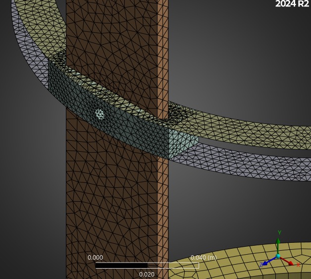
¶ Mesh
The same mesh was used as in the eigenvalue buckling analyses.
2025_C_ST_COMPOSITE_ABRs_FEA
Quadratic Elements were used with the "Automatic" element type. The automatic element type allowed us to reach the highest quality, and Hex Dominants were not adapted to these models who's surface to volume ratio is too high.
"Quality" was set to 0.95 in Ansys.
No refinements were applied.
Identical to the eigenvalue buckling analyses, due to file size constraints.
¶ Outputs
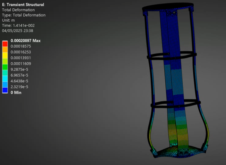
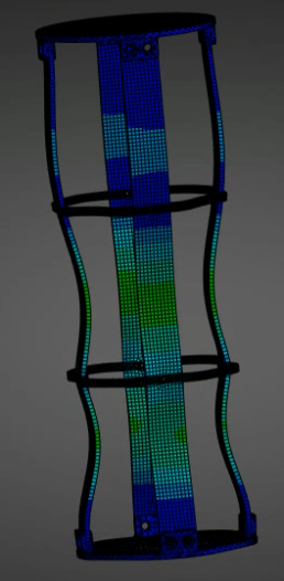
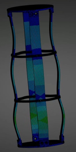
The output was a video of the pressurant bay, from which 3 screenshots were taken:
 |
 |
 |
|---|
The most interesting thing to take from these images is that:
- As opposed to the engine bay dynamical analysis, deformation reaches all 3 segments of the rods, and not insignificantly so!
- The deformations, and displacements, are altogether very small and this is a good sign for Firehorn 1.
¶ Interpretation
¶ Simulation validity
The simulation seems quite accurate. For one, the geometries used in this simulation were designed for a 15kN motor, and the factor of safety found for these same geometries in this simulation are about 2* the ones found in past simulations. Furthermore, with results that seem visually intuitive (deformation shape, modes that ressemble previous buckling analyses, fins with a significantly lower impact compared to the motor), we think this simulation gives a good overview of the pressurant bay's behavior during the rocket's liftoff.
¶ Conculsions
While we had to make quite a few simplifications regarding the fins forces, and the time steps on the simulations, these simualtions do have value.
For one, the fins' forces are absolutely negligble. Compared to the motor, they have virtually no contribution to the deformation or stress, and this force only decreases over the flight's duration.
Secondly, we can validate the dynamical behavior of the pressurant bay during the initial flight stage (the most critical one), as no parts reach a point of failure.
The next steps for this simulation will be in the following document where similar simulations will be carried out on the Engine Bay, with 2 time set ups, and potentially multiple ABRs so we can compare them.